
Using flowable CVD to gap fill micro/nano structures for optical components

a micro/nano structure and optical component technology, applied in the field of forming optical components for display devices, can solve the problem of very slow film deposition rate of the ald process

Inactive Publication Date: 2020-01-02
APPLIED MATERIALS INC
View PDF6 Cites 1 Cited by
  • Summary
  • Abstract
  • Description
  • Claims
  • Application Information

AI Technical Summary

Benefits of technology

This patent relates to a method for making an optical component for a virtual reality or augmented reality display device. The method involves creating a layer with a pattern on a substrate, where the first layer has a specific refractive index. Another layer is then deposited on top of the first layer using a flowable chemical vapor deposition process. The refractive index of this second layer is lower than the first layer. The resulting optical component has improved performance and can be used in virtual or augmented reality devices.

Problems solved by technology

However, the film deposition rate of the ALD process is very slow.

Method used


Image

  • Using flowable CVD to gap fill micro/nano structures for optical components
  • Using flowable CVD to gap fill micro/nano structures for optical components
  • Using flowable CVD to gap fill micro/nano structures for optical components

Examples


Embodiment Construction

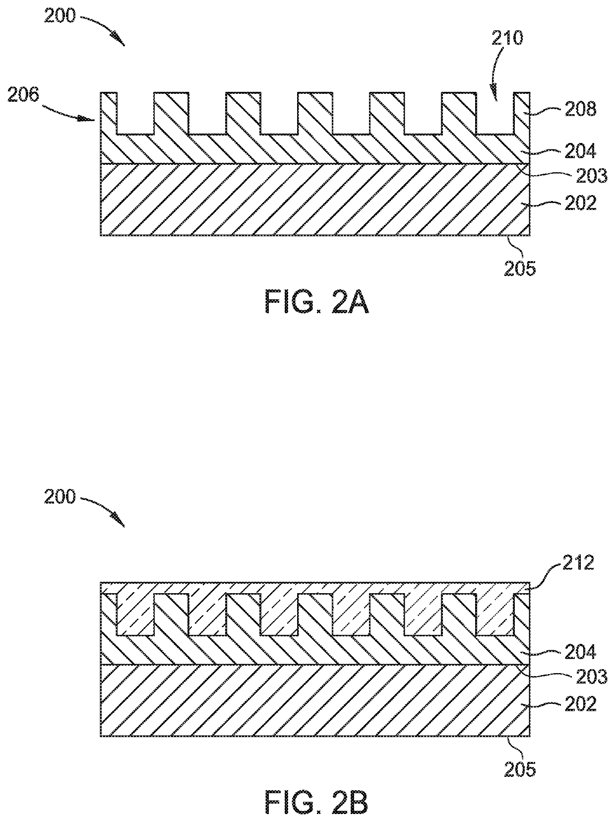
[0015]Embodiments of the present disclosure generally relate to a method for forming an optical component, for example, for a virtual reality or augmented reality display device. In one embodiment, the method includes forming a first layer having a pattern on a substrate, and the first layer has a first refractive index. The method further includes forming a second layer on the first layer by a flowable chemical vapor deposition (FCVD) process, and the second layer has a second refractive index less than the first refractive index.

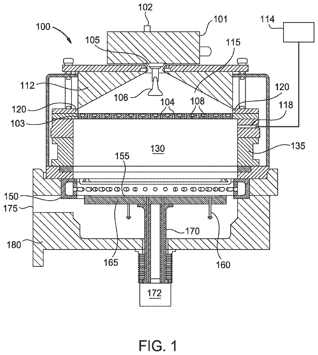
[0016]FIG. 1 is a schematic cross-sectional side view of a processing chamber 100 according to one embodiment described herein. The processing chamber 100 may be a deposition chamber, such as a CVD chamber. The processing chamber 100 may be configured at least to deposit a flowable film on a substrate. The processing chamber 100 includes a lid 112 disposed over a chamber wall 135, and an insulating ring 120 disposed between the lid 112 and the chamber wall...


PUM

PropertyMeasurementUnit
Temperatureaaaaaaaaaa
Refractive indexaaaaaaaaaa

Abstract

Embodiments of the present disclosure generally relate to a method for forming an optical component, for example, for a virtual reality or augmented reality display device. In one embodiment, the method includes forming a first layer having a pattern on a substrate, and the first layer has a first refractive index. The method further includes forming a second layer on the first layer by a flowable chemical vapor deposition (FCVD) process, and the second layer has a second refractive index less than the first refractive index.

Description

CROSS-REFERENCE TO RELATED APPLICATIONS[0001]This application claims priority to U.S. Provisional Patent Application Ser. No. 62 / 692,255, filed on Jun. 29, 2018, which herein is incorporated by reference.BACKGROUNDField[0002]Embodiments of the present disclosure generally relate to display devices for augmented, virtual, and mixed reality. More specifically, embodiments described herein provide a method for forming an optical component for a display device.Description of the Related Art[0003]Virtual reality is generally considered to be a computer generated simulated environment in which a user has an apparent physical presence. A virtual reality experience can be generated in 3D and viewed with a head-mounted display (HMD), such as glasses or other wearable display devices that have near-eye display panels as lenses to display a virtual reality environment that replaces an actual environment.[0004]Augmented reality enables an experience in which a user can still see through the dis...

Claims


Application Information

Patent Timeline
IPC IPC(8): G02B5/18G03F7/00C23C16/40C23C16/56
CPCG03F7/0007C23C16/56C23C16/402G02B5/1857G03F7/0005G02B1/10G02B27/4272G02B27/0172G02B2027/0109C23C16/45565C23C16/452C23C16/045C23C28/04C23C16/4405C23C28/042G02B5/0883G02B1/04
Inventor FU, JINXINGODET, LUDOVICMCMILLAN, WAYNE
Owner APPLIED MATERIALS INC
Learn More