Wind turbine

a wind turbine and rotor technology, applied in the direction of machines/engines, sliding contact bearings, mechanical equipment, etc., can solve the problems of uneven load resting on the yaw bearing arrangement, tilting moment or tilting force, and large forces on the top sliding pads in the fron

Active Publication Date: 2020-01-16
SIEMENS GAMESA RENEWABLE ENERGY AS
View PDF0 Cites 0 Cited by
  • Summary
  • Abstract
  • Description
  • Claims
  • Application Information

AI Technical Summary

Problems solved by technology

In modern wind turbines of the direct drive technology an uneven load rests on the yaw bearing arrangement due to the heavy weight of the generator and of the large rotors arranged at the hub.
This results in a tilting moment or tilting force and thus in larger forces on the top sliding pads in the front, e.g. in the direction of the hub, and the lower sliding pads in the rear of the nacelle.
Because of the increased force resting on these local sliding pads or sliding shoes an uneven wear occurs in the slidi

Method used


Image

  • Wind turbine
  • Wind turbine
  • Wind turbine

Examples


Embodiment Construction

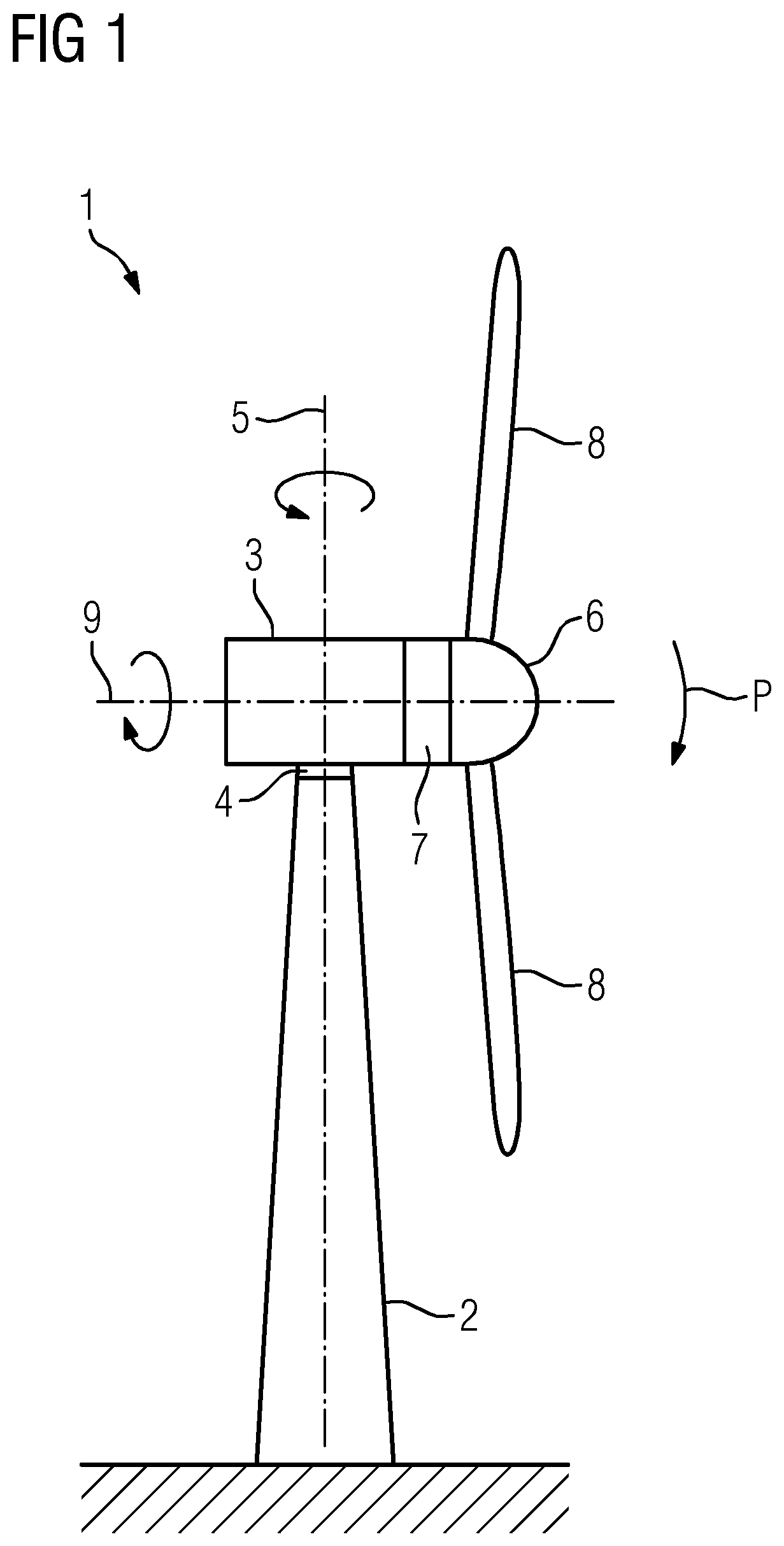
[0025]FIG. 1 schematically illustrates a wind turbine 1 comprising a tower 2. At the top of the tower 2 a nacelle 3 is mounted. The nacelle 3 is rotatable connected with the tower 2 via a yaw bearing arrangement 4. The yaw bearing arrangement 4 enables a rotational movement of the nacelle 3 around a yaw axis 5 relative to the tower, wherein the yaw axis 5 is orientated substantially vertically.

[0026]A hub 6 is rotatable connected to the nacelle 3 via a main bearing. The hub 6 is a part of the so called rotor, which rotor transfers rotational energy from the hub 6 to a generator 7, which generator produces electric energy from the rotational energy. For rotating the hub 6 a plurality of rotor blades 8 are arranged at the hub, which rotor blades 8 can, if need be, pitched relative to the hub 6. The hub 6 respectively the rotor blades 8 are rotatable around a substantially horizontal axis 9. The generator 7 is preferably directly connected to the rotor respectively the hub 6, the wind ...


PUM


Abstract

Provided is a wind turbine including a tower and a nacelle rotatable relative to the tower by means of a yaw bearing arrangement having a yaw ring fixed relative to the tower, several upper sliding pads arranged between the upper side of the yaw ring and a sliding structure of the nacelle and several lower sliding pads arranged between the lower side of the yaw ring and the sliding structure, wherein the sliding pads are fixed to the yaw ring and that at least one radial opening is provided in the sliding structure allowing access to the upper or lower sliding pads.

Description

CROSS-REFERENCE TO RELATED APPLICATIONS[0001]This application claims priority to European application No. 18182559.7, having a filing date of Jul. 10, 2018, the entire contents of which are hereby incorporated by reference.FILED OF TECHNOLOGY[0002]The embodiments of the invention relate to a wind turbine, comprising a tower and a nacelle rotatable relative to the tower by means of a yaw bearing arrangement comprising a yaw ring fixed relative to the tower, several upper sliding pads arranged between the upper side of the yaw ring and a sliding structure of the nacelle and several lower sliding pads arranged between the lower side of the yaw ring and the sliding structure.BACKGROUND[0003]For adjusting the orientation of the hub of a wind turbine comprising the rotor blades the nacelle, to which the hub is connected, is rotatable relative to the tower. A yaw bearing arrangement allows this rotation of the nacelle. This yaw bearing comprises a yaw ring, which is fixed relative to the t...

Claims


Application Information

Patent Timeline
IPC IPC(8): F03D80/70F16C17/02
CPCF03D80/70F05B2240/50F16C17/107F16C2360/31F16C17/04F03D7/0204F03D80/50Y02E10/72F16C17/10
Inventor DAMGAARD, STEENNIELSEN, RUNE
Owner SIEMENS GAMESA RENEWABLE ENERGY AS
Why Eureka
Try Eureka