Electric driving device and electric power steering device

Active Publication Date: 2020-01-23
HITACHI ASTEMO LTD
View PDF0 Cites 1 Cited by
  • Summary
  • Abstract
  • Description
  • Claims
  • Application Information

AI Technical Summary

Benefits of technology

[0016]As the power conversion circuits are arranged from the center to the periphery of the mounting substrate in the present invention, it is possible to attain a shorter wiring length and smal

Problems solved by technology

In the case where a single power conversion circuit is used as in the conventional power steering device, it becomes impossible to drive the electric motor in the event of a failure such as ground fault so that there arises a problem of deterioration in steering operability due to a decrease in assist force.
In this case, there arises a problem that the axial length of the ECU housing becomes

Method used


Image

  • Electric driving device and electric power steering device
  • Electric driving device and electric power steering device
  • Electric driving device and electric power steering device

Examples


Example

[0052]In order to meet such a demand, the first embodiment of the present invention proposes the following mounting technique.

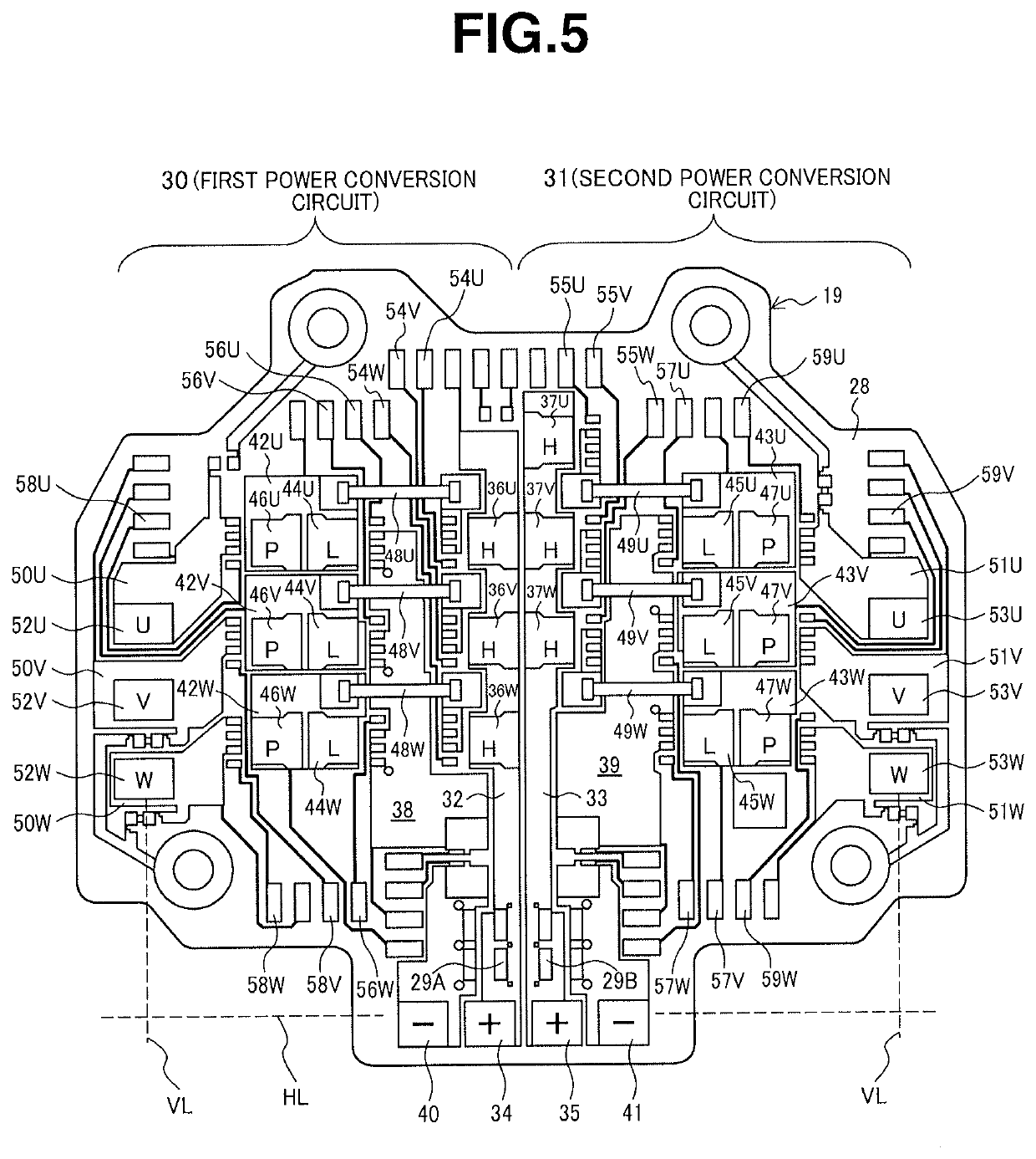
[0053]The power conversion circuit portion according to the first embodiment is so structured that: two positive-electrode-side power lines are arranged in the vicinity of the center of the mounting substrate from an outer peripheral side to an inner side of the mounting substrate; negative-electrode-side power lines and power conversion circuits for drive control of the electric motor are arranged on both sides of the mounting substrate with respect to the positive-electrode-side power lines; and output terminals for connection to the electric motor are arranged on the mounting substrate at a location outward of the power conversion circuits.

[0054]In the first embodiment, the power conversion circuits are arranged from the center to the periphery of the mounting substrate. This arrangement leads to a shorter wiring length and smaller mounting area for the po...

Example

[0130]Next, the second embodiment of the present invention will be described below with reference to FIG. 8. The second embodiment is basically similar in configuration to the first embodiment, except for the arrangement positions of the high-potential-side MOSFETs and the arrangement positions of the jumper wires between the high-potential-side MOSFETs and the low-potential-side MOSFETs. The basic features and effects of the second embodiment are the same as those of the first embodiment. The following explanation will be given of the other features and effects.

[0131]As the configuration of the second embodiment is basically similar to that of the first embodiment, any structural parts and portions, other than those that need to be explained below, are not given reference numerals in FIG. 8 but could be understood by reference to FIG. 5.

[0132]As shown in FIG. 8, the first power conversion circuit 30 of the second embodiment is the same in configuration as that of the first embodime...

Example

[0137]The third embodiment of the present invention will be next described below with reference to FIG. 9. The third embodiment is different from the first embodiment, in that the positional relationship of the positive- and negative-electrode-side power lines is changed such that the positive-electrode-side power lines are arranged adjacent to and outward of the negative-electrode-side power lines; and the arrangement directions of the high-potential-side MOSFETs and the low-potential-side MOSFETs are changed according to the positional relationship of the positive- and negative-electrode-side power lines.

[0138]The basic features and effects of the third embodiment are the same as those of the first embodiment. The following explanation will be given of the other features and effects.

[0139]In FIG. 9, any structural parts and portions other than those that need to be explained below are not given reference numerals. As the configuration of the gate signal lines and the like of the t...


PUM


Abstract

Disclosed is an electric driving device in which: two positive-electrode-side power lines (32, 33) are arranged from an outer peripheral side to an inner side of a mounting substrate (19); power conversion circuits (36, 37; 44, 45; 46, 47) are arranged on both sides of the mounting substrate, with respect to the positive-electrode-side power lines, to perform drive control of an electric motor; and output terminals (52, 53) are arranged on the mounting substrate at a location outward of the power conversion circuit so as to establish a connection to the electric motor. As the power conversion circuits are disposed from the center to the periphery of the mounting substrate, it is possible to decrease the wiring length and circuit mounting area of the mounting substrate (19) and suppress a radial size increase of the mounting substrate on which the redundant power conversion circuits are mounted.

Description

FIELD OF THE INVENTION[0001]The present invention relates to an electric driving device and an electric power steering device, each of which has integrated therein an electronic control unit.BACKGROUND ART[0002]In the field of general industrial machinery, mechanical control elements are driven by electric motors. There has recently been started the use of a so-called mechanically and electrically integrated type electric driving device in which an electronic control unit with a semiconductor element and the like is integrally mounted on an electric motor to control a rotation speed and torque of the electric motor.[0003]One example of the mechanically and electrically integrated type electric driving device is an electric power steering device for a vehicle, which is adapted to detect a rotational direction and torque of a steering shaft caused by driver's operation of a steering wheel and drive an electric motor based on the detection results such that the electric motor rotates i...

Claims


Application Information

Patent Timeline
IPC IPC(8): B62D5/04H02K11/33
CPCH02K11/33B62D5/0424H02K2211/03B62D5/0406B62D5/046H02M7/003H02M7/493B62D5/04
Inventor YATSUGI, TOMISHIGESAKAI, TOSHIHIKO
Owner HITACHI ASTEMO LTD
Why Eureka
Try Eureka