Wind turbine blade and a wind turbine

a wind turbine blade and blade technology, applied in the direction of wind turbines, wind turbine components, wind turbines, etc., can solve the problems of high wind force on long rotor blades, and the more likely to be detected and repaired, the higher the probability of failures in further connection

Active Publication Date: 2020-01-23
SIEMENS GAMESA RENEWABLE ENERGY AS
View PDF0 Cites 6 Cited by
  • Summary
  • Abstract
  • Description
  • Claims
  • Application Information

AI Technical Summary

Benefits of technology

[0009]The inventor found out that material transitions form critical points when current is conducted from one material to another material. These critical points may arise due to different conductivities or different conductivity anisotropies of the materials in the overlapping portion. The proposed overlapping portion between the support element and the fiber material avoids arcing or sparking and, thus, delamination in the support element when conducting a current, for example, having 86 kA. Thus, damages of the wind turbine blade may be avoided when a lightning strike is intercepted by the wind turbine blade.
[0037]Three or more of such fiber materials and such electrical conductors may be provided. The electrical conductor and the further electrical conductor may be provided as one electrical conductor extending in longitudinal direction of the wind turbine blade. Thus, it is possible to increase the number of connections between the support element and the electrical conductors or conductor providing a redundant system.

Problems solved by technology

Long rotor blades experience high wind forces.
Furthermore, failures in the further connection are more likely to be detected and repaired prior to a collapse of the structure.

Method used


Image

  • Wind turbine blade and a wind turbine
  • Wind turbine blade and a wind turbine
  • Wind turbine blade and a wind turbine

Examples


Embodiment Construction

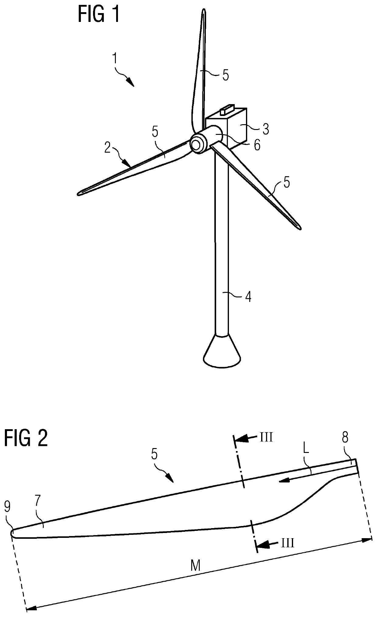
[0058]FIG. 1 shows a wind turbine 1. The wind turbine 1 comprises a rotor 2 connected to a generator (not shown) arranged inside a nacelle 3. The nacelle 3 is arranged at an upper end of a tower 4 of the wind turbine 1.

[0059]The rotor 2 comprises three wind turbine blades 5. The wind turbine blades 5 are connected to a hub 6 of the wind turbine 1. Rotors 2 of this kind may have diameters ranging from, for example, 30 to 200 meters or even more. The wind turbine blades 5 are subjected to high wind loads. At the same time, the wind turbine blades 5 need to be lightweight. For these reasons, wind turbine blades 5 in modern wind turbines 1 are manufactured from fiber-reinforced composite materials. Oftentimes, glass or carbon fibers in the form of unidirectional fiber mats are used.

[0060]FIG. 2 shows a wind turbine blade 5. The wind turbine blade 5 comprises an aerodynamically designed portion 7 which is shaped for optimum exploitation of the wind energy and a blade root 8 for connectin...


PUM

PropertyMeasurementUnit
angleaaaaaaaaaa
angleaaaaaaaaaa
angleaaaaaaaaaa

Abstract

Provided is a wind turbine blade for a wind turbine, the wind turbine blade including a support element having first fibers being electrically conductive, and a fiber material having second fibers being electrically conductive, wherein the fiber material has a free portion and an overlapping portion which is at least partially attached and electrically connected to the support element, wherein an extension direction of the second fibers changes along an extension path of the second fibers, wherein a first angle is provided between the second fibers in the overlapping portion and the first fibers, wherein a second angle is provided between the second fibers in the free portion and the first fibers, and wherein the second angle is larger than the first angle.

Description

CROSS-REFERENCE TO RELATED APPLICATIONS[0001]This application claims priority to EP Application No. 18183962.2, having a filing date of Jul. 17, 2018, the entire contents of which are hereby incorporated by reference.FIELD OF TECHNOLOGY[0002]The following relates to a wind turbine blade for a wind turbine and a wind turbine comprising such a wind turbine blade.BACKGROUND[0003]Modern wind turbine rotor blades are built from fiber-reinforced plastics. A rotor blade typically comprises an airfoil having a rounded leading edge and a sharp trailing edge. The rotor blade is connected with its blade root to a hub of the wind turbine. Further, the rotor blade is connected to the hub by means of a pitch bearing that allows a pitch movement of the rotor blade. Long rotor blades experience high wind forces.[0004]Rotor blades may be made of two half-shells connected to each other. Further, a web, in particular a shear web, may be arranged between the two half-shells to reinforce the rotor blade...

Claims


Application Information

Patent Timeline
Patent Type & Authority Applications(United States)
IPC IPC(8): F03D80/30F03D1/06
CPCF03D80/30F05B2240/2211F05B2280/6003F03D1/0683F05B2280/2006F03D1/0675F05B2280/6013Y02E10/72F05B2250/314F05B2250/324
Inventor CHRISTIANSEN, THOMAS LEHRMANNGIROLAMO, DONATO
Owner SIEMENS GAMESA RENEWABLE ENERGY AS
Why Eureka
Try Eureka