Dispensing System

a technology of dispense system and dispenser, which is applied in the direction of containers, bottles, applications, etc., can solve the problems of difficult service or replacement of parts, time-consuming and messy filling operation, and inability to provide soap and detergent bars for multiple use, so as to facilitate the dispense system cleaning, increase compliance with rules, and produce a smoother and visually appealing form

Active Publication Date: 2020-01-30
BRADLEY MARK ANTHONY
View PDF0 Cites 5 Cited by
  • Summary
  • Abstract
  • Description
  • Claims
  • Application Information

AI Technical Summary

Benefits of technology

[0022]The housing can conveniently be provided in a range of types of plastics, using injection moulding techniques or otherwise. The housing can be provided with an internal pump—and be operated under manual control or an automatic system or otherwise. The pump can be arranged such that a liquid is dispensed remote form the container or is the liquid is dispensed by means of a tap associated with, for example, the housing. It will be appreciated that the housing and /or the outlet tubes can be colour coded to assist in a differentiation of the liquids contained therein, the housing and the tubes being provided in a range of standard plastics materials, for example, being provide with anti-microbial plastics product protection solutions, being plastics additives such as heparin. Additional...

Problems solved by technology

Providing soap and detergent bars for multiple use poses a problem because some individuals dislike using a soap bar which had been used before by a person who may have left a wet, soggy soap bar.
The filling operation tends to be time-consuming and messy.
Such dispensers are usually mounted to a wall, making some parts difficult to service or replace.
Also, it is often difficult to feed the product directly into the dispenser container by pouring the liquid from a big supply tank because the dispenser is so close to the wall.
Prior dispensers have typically been of relatively complex construction, frequently using a large number of parts, the assembly of which entails substantial labour.
For example, some dispensers employ a complex pressuring system to dispense the liquid, for example, if the liquid is required to be available at several areas within a production facility.
These devices result in mechanical difficulties and are subject to undue wear and fairly rapid breakdown.
Some difficulties may also arise when screws must ...

Method used


Image

  • Dispensing System
  • Dispensing System
  • Dispensing System

Examples


Embodiment Construction

[0035]There will now be described, by way of example only, the best mode contemplated by the inventor for carrying out the present invention. In the following description, numerous specific details are set out in order to provide a complete understanding to the present invention. It will be apparent to those skilled in the art, that the present invention may be put into practice with variations of the specific. For the avoidance of doubt, the term closure refers to devices used to close or seal a bottle, jug, jar, tube, can, container, barrel, keg etc. Closures can be a cap, cover, lid, plug, bung, etc.

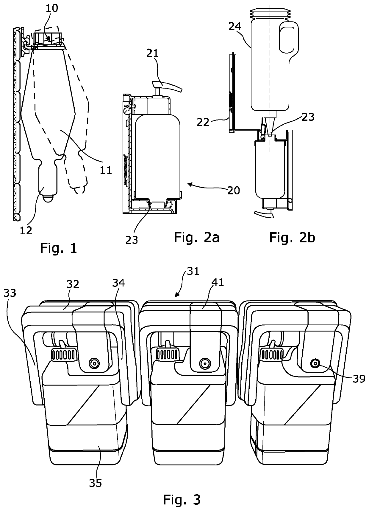
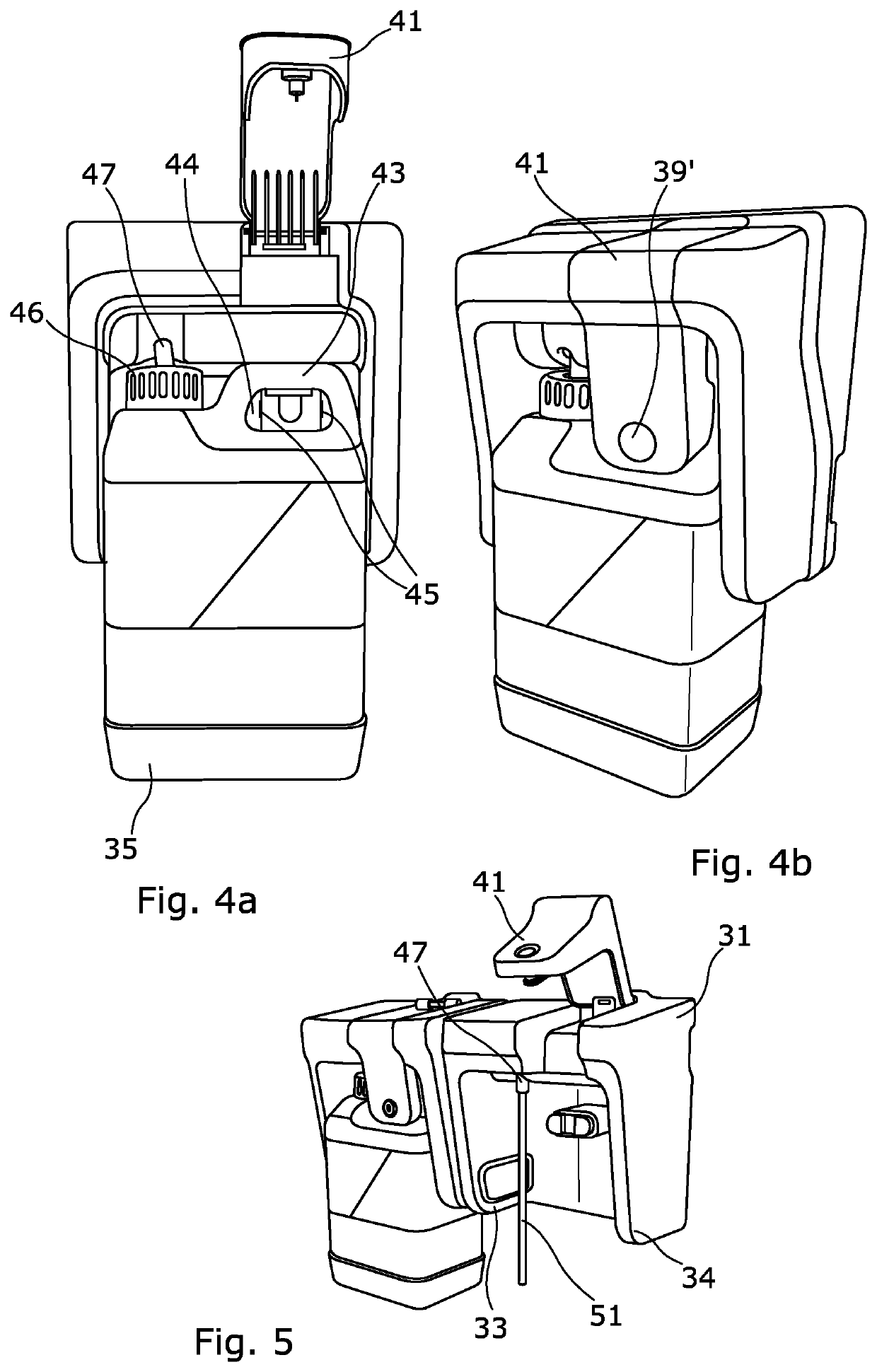
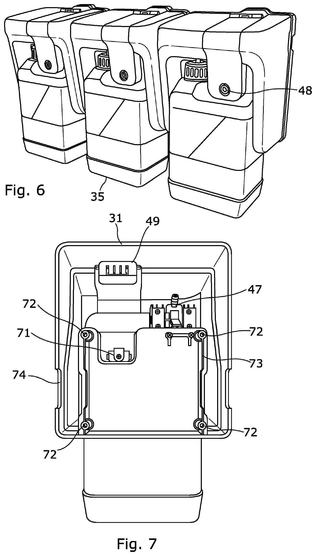
[0036]Referring now to FIGS. 3, 4a, 4b, 5&6, there are shown, respectively, a front view of three dispensing systems in accordance with the present invention; a front view of a single dispensing system, with a container in position and having a securing member in a release position; a perspective view of two dispensing systems, one having a liquid container in place and the other havi...


PUM


Abstract

The present invention relates to dispensing systems that include containers used to contain fluids that need to be dispensed in controlled quantities. In particular, the present invention relates to a dispensing system which can be readily and securely fastened to the walls and other operating surfaces associated with bathrooms, changing rooms, machine shops and the like. In water closets at places of work, hospitals, laboratories, workshops and similar places, there are many individuals who require access to liquids such as liquid soap, oils and production process chemicals etc. usually have a reservoir that must be filled from a larger supply container. The filling operation tends to be complicated and thus time-consuming and with the likelihood of the creation of a mess. It is often difficult to feed the product directly into the dispenser container by pouring the liquid from a big supply tank. It is important that the fluids—whether for lubricating, cleaning or production processes—are managed such that only the correct fluids are. In the installation of a liquid dispensing system, factors of convenience in ensuring that the dispensers are maintained at a suitable level must be weighed against security of product. Many “universal” systems relinquish security and stock control and/or are complex to utilise. The present invention seeks to provide a solution to the problems addressed above. The present invention seeks to provide a dispensing system and a container that enables simple checking of fluid levels and simple re-filling thereof.

Description

CROSS-REFERENCE TO RELATED APPLICATIONS[0001]Application No.Date FiledTitleCurrent applicationHerewithDispensing SystemIs a National Phase Entry (371) filingof:PCT / IB2017 / 001337Oct. 12,Dispensing System With Securement2017which is a PCT filing of Great Britainapplication:GB1617503.6Oct. 14,Dispensing System2016the entire specification of each of which are incorporated herein by reference.BACKGROUNDField of Invention[0002]The present invention relates to dispensing systems that include containers used to contain fluids that need to be dispensed in controlled quantities. In particular, the present invention relates to a dispensing system which can be readily and securely fastened to the walls and other operating surfaces associated with manufacturing facilities, machine shops, bathrooms, changing rooms and the like.Background to the Invention[0003]In water closets at places of work, hospitals, laboratories, and similar places, there are many individuals who require access to cleaning ...

Claims


Application Information

Patent Timeline
IPC IPC(8): A47K5/12
CPCA47K2010/3246A47K5/12B65D23/00B65D2211/00
Inventor BRADLEY, MARK ANTHONY
Owner BRADLEY MARK ANTHONY
Why Eureka
Try Eureka