
Real-time optical spectro-temporal analyzer and method

a real-time optical and spectro-temporal analyzer technology, applied in the direction of optical radiation measurement, instruments, spectrometry/spectrophotometry/monochromators, etc., can solve the problem that the tss spectroscopy (tss) is invalid for continuous-wave (cw)/quasi-cw signals, and the output is drastic, so as to facilitate the comprehensive study of various complex phenomena and the understanding of complex nonlinear dynamics

Active Publication Date: 2020-01-30
THE UNIVERSITY OF HONG KONG
View PDF0 Cites 2 Cited by
  • Summary
  • Abstract
  • Description
  • Claims
  • Application Information

AI Technical Summary

Benefits of technology

The patent describes a method called ROSTA that can analyze the structure of optical fields in real-time. By measuring the intensity of light as it changes over time, ROSTA can help researchers better understand the complex nonlinear dynamics of optical systems. This makes ROSTA a powerful tool for studying various complex phenomena in optical nonlinear systems.

Problems solved by technology

However, any perturbation in the laser cavity can induce a drastic change in the output.
These unpredictable nonlinear disturbances occur in an ultrafast transition way.
To visualize and diagnose these intriguing nonlinear dynamics, ultrafast detection simultaneously in both time and frequency domains is essential, which unfortunately is a historical problem owing to limitations in both spectro-temporal resolution and recording length.
However, despite its ability to capturing spectral information of ultra-short pulses (femtosecond-picosecond (fs-ps)), TS spectroscopy (TSS) is invalid for continuous-wave (CW) / quasi-CW signals.
Consequently, any CW / quasi-CW component involved in the optical dynamics will be concealed by the TS spectroscope, resulting in defective information, particularly for those ultrafast nonlinear dynamic events evolved from CW / quasi-CW states.
Unfortunately, the working wavelength is very limited (few pm), which in return disables the spectral visualization of ultrashort pulses.
U.S. Pat. No. 6,665,069 discloses a temporal analyzer, but it can only provide frequency information in a very slow manner, similar to a conventional optical spectrum analyzer (OSA) and with no time-domain information.
However, it can only provide frequency information, not time-domain information.

Method used


Image

  • Real-time optical spectro-temporal analyzer and method
  • Real-time optical spectro-temporal analyzer and method

Examples


Embodiment Construction

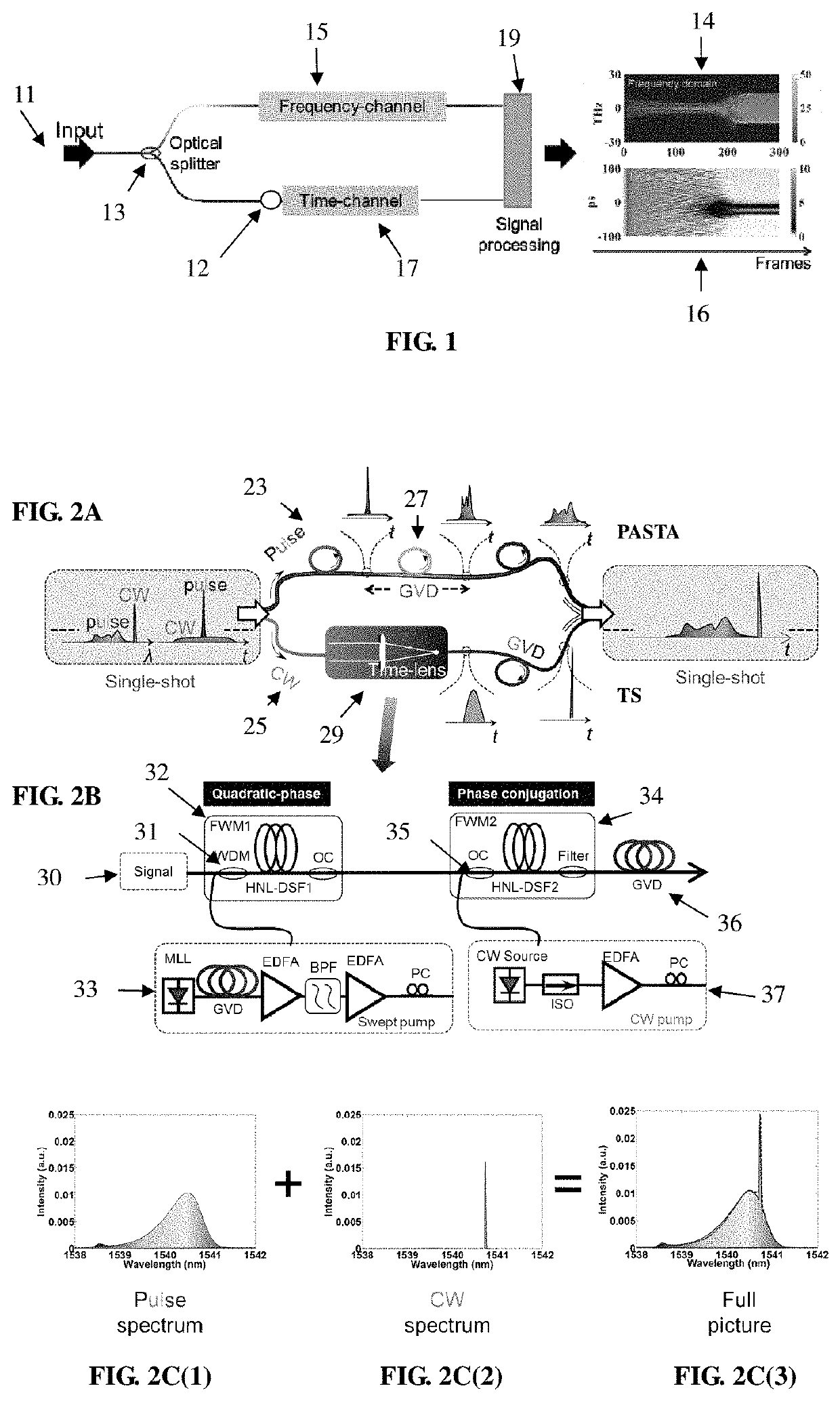
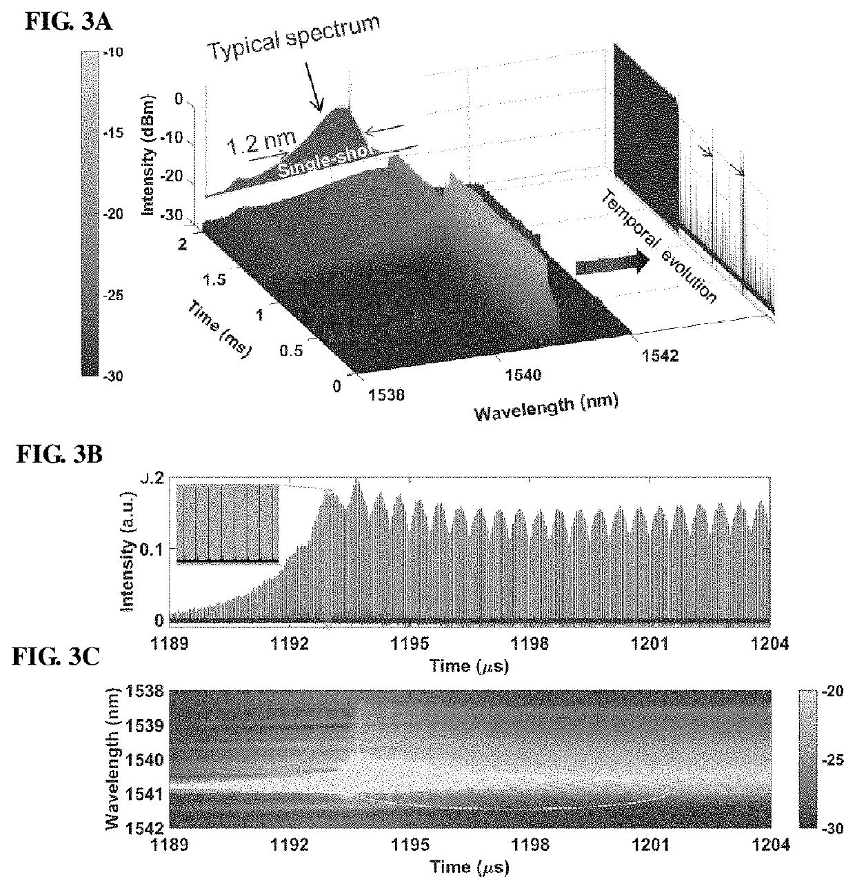
[0020]FIG. 1 shows an overview of a versatile ROSTA system and method according to an exemplary embodiment of the present invention. Basically, the optical signal is simultaneously diagnosed in two different domains, i.e., frequency domain / channel and time domain / channel. Then, a comprehensive picture of the spectro-temporal information of the optical signal is obtained through data processing.

[0021]An optical signal is launched into the ROSTA system through a fiber tap coupler at input 11. The signal is passed to an optical splitter 13 which directs part of the signal to a frequency channel 15 and part to a time channel 17. Thus, ROSTA captures the non-repeated dynamic event in both time and frequency domains. In the time domain, ROSTA directly monitors the intensity evolution through a photodiode (PD) 12. In the Frequency Domain, ROSTA captures the spectral information with two sub-channels specified for quasi-CW and short-pulse components, respectively. The frequency and time dom...


PUM


Abstract

An optical signal analyzing apparatus enables real-time and single-shot analysis simultaneously in both time and frequency domains with spectro-temporal analysis. The apparatus includes a fiber tap coupler for receiving an input optical signal from continuous wave (CW) to ultra-short pulses (femtosecond-picosecond). An optical splitter directs part of the signal to a frequency channel and part to a time channel A photodiode in the time channel directly monitors the intensity evolution and converts it to an electrical signal. In the frequency channel, two sub-channels are provided: one for CW / quasi-CW and one for short-pulse components. A signal processor analyses the time- and frequency-domain data from the time channel and frequency channel and displays the temporal and spectral evolutions simultaneously, so that the two different pieces of information of a non-repeated dynamic event can be correlated in different domains.

Description

FIELD OF THE INVENTION[0001]The present invention relates to optical signal analyzing apparatus and method, and more particularly to an apparatus and method that enables real-time analysis of a laser output simultaneously in both time and frequency domains.BACKGROUND OF THE INVENTION[0002]Optical sources have gained significant popularity over last decades owing to their widespread applications. Their various playgrounds include optical communication, material processing, astronomical exploration, biological imaging and other scientific studies, e.g., optical arbitrary waveform generation and coherent spectroscopy, to name a few. See, G P. Agrawal, Fiber-Optic Communication Systems, 3rd ed. (Wiley, New York, 2002); L. Shah et al., “Waveguide writing in fused silica with a femtosecond fiber laser at 522 nm and 1 MHz repetition rate,”Opt. Express 13, 1999-2006 (2005); R. R. Gattass and E. Mazur, “Femtosecond laser micromachining in transparent materials,”Nat. Photon. 2(4), 219-225 (20...

Claims


Application Information

Patent Timeline
Patent Type & Authority Applications(United States)
IPC IPC(8): G01J3/18H04J14/02G01J3/02
CPCH04J14/02G01J3/0218G01J3/1895G01J1/00
Inventor WONG, KIN YIP, KENNETHWEI, XIAOMINGLI, BOWENYU, YINGZHANG, CHI
Owner THE UNIVERSITY OF HONG KONG
Learn More