Riveting and grinding assembly for the nozzle of a screw shaft valve

Active Publication Date: 2020-02-06
DONGGUAN UNIV OF TECH
View PDF0 Cites 29 Cited by
  • Summary
  • Abstract
  • Description
  • Claims
  • Application Information

AI Technical Summary

Benefits of technology

[0003]The present invention relates to a riveting and grinding assembly for the nozzle of a screw shaft valve. First, put threaded pipe into a carrier assembly by a loading device. Then the carrier assembly rotates counterclockwise and rotates to a prevalve pipe feeding device to press the threaded pipe into a valve seat. Next a v

Problems solved by technology

Existing technology requires an operator to assemble Tee shaped screw shaft valve by hand

Method used


Image

  • Riveting and grinding assembly for the nozzle of a screw shaft valve
  • Riveting and grinding assembly for the nozzle of a screw shaft valve
  • Riveting and grinding assembly for the nozzle of a screw shaft valve

Examples


Embodiment Construction

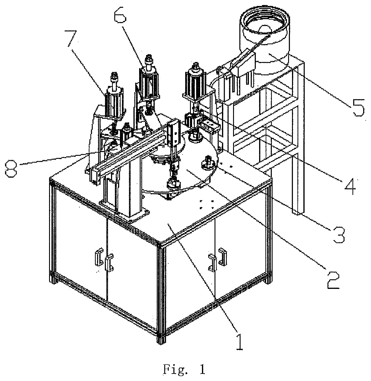
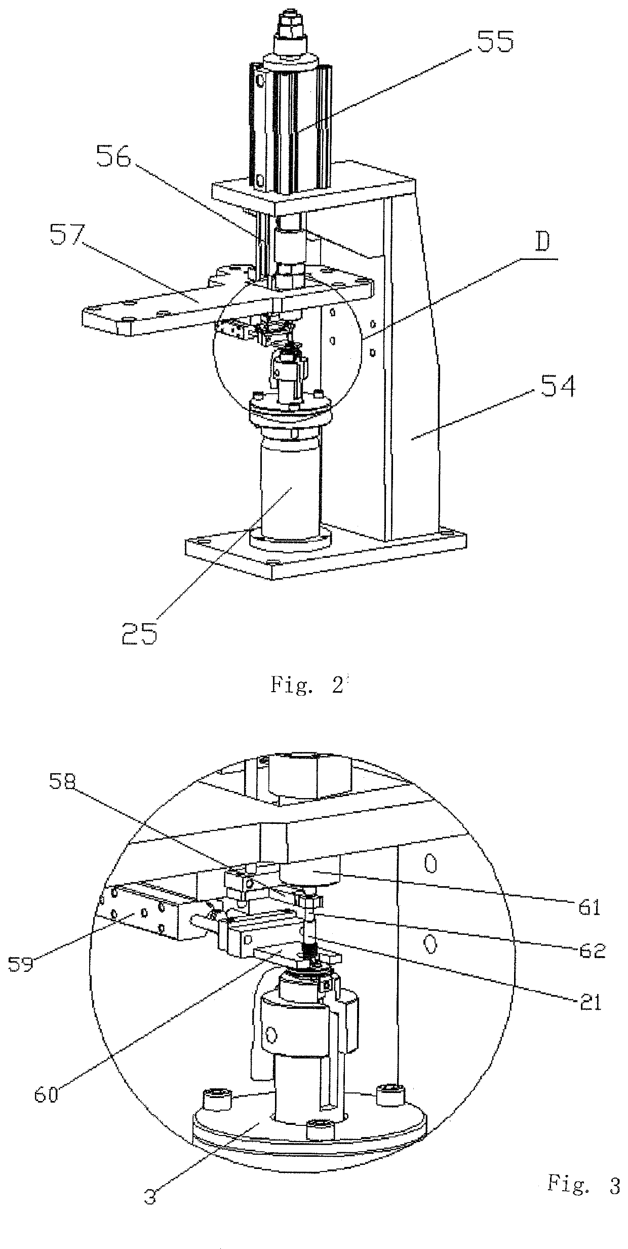
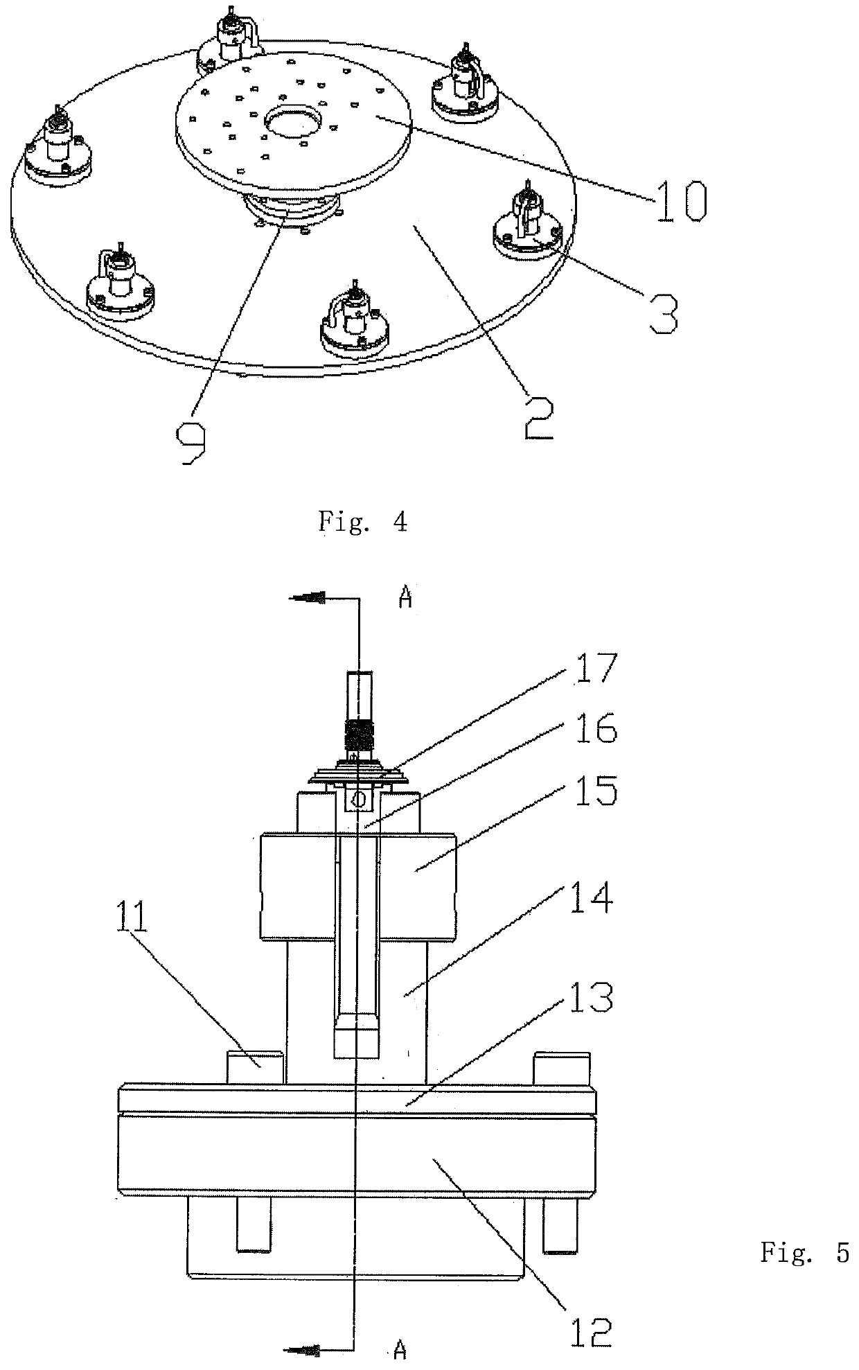
[0028]Component parts in the FIGURES are:[0029]1. rack,[0030]2. turntable,[0031]3. carrier assembly,[0032]4. valve pipe feeding device,[0033]5. vibration feeding pan,[0034]6. valve pipe preloading device,[0035]7. valve pipe riveting device,[0036]8. valve pipe grinding device,[0037]9. support shaft,[0038]10. upper supporting disc[0039]11. fixing bolt,[0040]12. carrier seat,[0041]13. carrier cover plate,[0042]14. carrier positioning axis,[0043]15. loading seat,[0044]16. positioning slot,[0045]17. screw shaft valve body,[0046]18. carrier damping spring,[0047]19. side valve pipe,[0048]20. valve flange,[0049]21. threaded pipe,[0050]22. valve seat,[0051]23. side positioning plate,[0052]24. lower valve tube[0053]25. carrier support,[0054]26. loading rack,[0055]27. push-in lever,[0056]28. push-in guide plate,[0057]29, feed cylinder[0058]30. guide tube,[0059]31. pushing cylinder,[0060]32. dispensing base,[0061]33. joining guide cylinder,[0062]34. transverse feeding plate,[0063]35. distributi...


PUM


Abstract

The present invention generally relates to assembly equipment of valve body, especially to riveting and grinding assembly for nozzle of screw shaft valve. The invention may include a rack, a power control box, a turntable and a turntable divider. A carrier assembly which engages with the screw shaft valve body is installed on the edge of the turntable with uniform distribution. On the center part of the turntable, a support shaft which is installed on and fixed with the rack is vertically interposed and on the top of the support shaft, an upper supporting disc is installed. A valve pipe feeding device, a valve pipe preloading device, a valve pipe riveting device and a valve pipe grinding device which engage with the carrier assembly are installed on the said rack on the rotational direction of turntable. As the threaded pipe is put into the carrier assembly by valve pipe feeding device, the carrier assembly rotates counterclockwise along the turntable and rotates to the valve pipe feeding device to the press threaded pipe into the valve seat. Thereafter the carrier assembly rotates the valve pipe riveting device and rivets threaded pipe with a valve flange in order to finish assembling process. Finally, the carrier assembly rotates the valve pipe grinding device to grind nozzle of valve to finish grinding and riveting process of threaded pipe with high positioning accuracy of assembly and marvelous hermetic sealing.

Description

FIELD OF THE INVENTION[0001]The present invention relates generally to assembly equipment for valve bodies, and more especially to a riveting and grinding assembly for the nozzle of a screw shaft valve.BACKGROUND OF THE INVENTION[0002]Screw shaft valve 17, as shown in FIG. 13, may include a valve seat 22 whose lower part is connected to a lower valve tube 24. To the side of the valve seat 22, a r-type side valve pipe is connected. And on its upper end, a valve flange 20 which rivets the threaded pipe 21 on the upper end is connected 20. To the side of the valve flange 20, a side positioning plate 23 is installed. Existing technology requires an operator to assemble Tee shaped screw shaft valve by hand which is not efficient and accurate enough and the hermetic sealing is not satisfactory. Acceptance rate and production efficiency are influenced. In addition, as threaded pipe directly rivets valve flange, burrs from nozzle of screw shaft valve will exist, which will further influence...

Claims


Application Information

Patent Timeline
IPC IPC(8): B21J15/14B24B19/00
CPCB24B19/00F16K27/00B21J15/14B23P23/04B24B27/0069B24B9/005B24B9/007B23P15/001B23P21/006B23Q39/046B23Q39/044Y10T29/53778Y10T29/5128Y10T29/5377Y10T29/513Y10T29/5373
Inventor DENG, JUNHE, CHULIANG
Owner DONGGUAN UNIV OF TECH
Why Eureka
Try Eureka