Behind casing wash and cement

Active Publication Date: 2020-02-06
CONOCOPHILLIPS CO
View PDF0 Cites 6 Cited by
  • Summary
  • Abstract
  • Description
  • Claims
  • Application Information

AI Technical Summary

Benefits of technology

[0015]The inventors have realized or conceived of a number of things which had not previously been appreciated regarding jet type washing in a P/W/C operation. They believed that any of a variety of factors such as the distance between the wash head and the inside wall of the casing, the number and size of perforations in the casing, the JET dissipation, the weight and rheology of the washing fluid, the weight, rheology or compressive strength of the annulus content, the work string RPM and movement, the hole angle, the original borehole effective ID, the flow and size of or over nozzles, the nozzle

Problems solved by technology

No onshore test rig existed (to the inventors' knowledge) suitable for this task.
In addition a large amount of CFD modelling has been done, and the physical tests results used to corroborate the CFD results.
It appears that, if washing is performed in an upward direction, debris may be displaced upwards in the annulus and then fall back down, negating the effect of

Method used


Image

  • Behind casing wash and cement
  • Behind casing wash and cement
  • Behind casing wash and cement

Examples


example 1

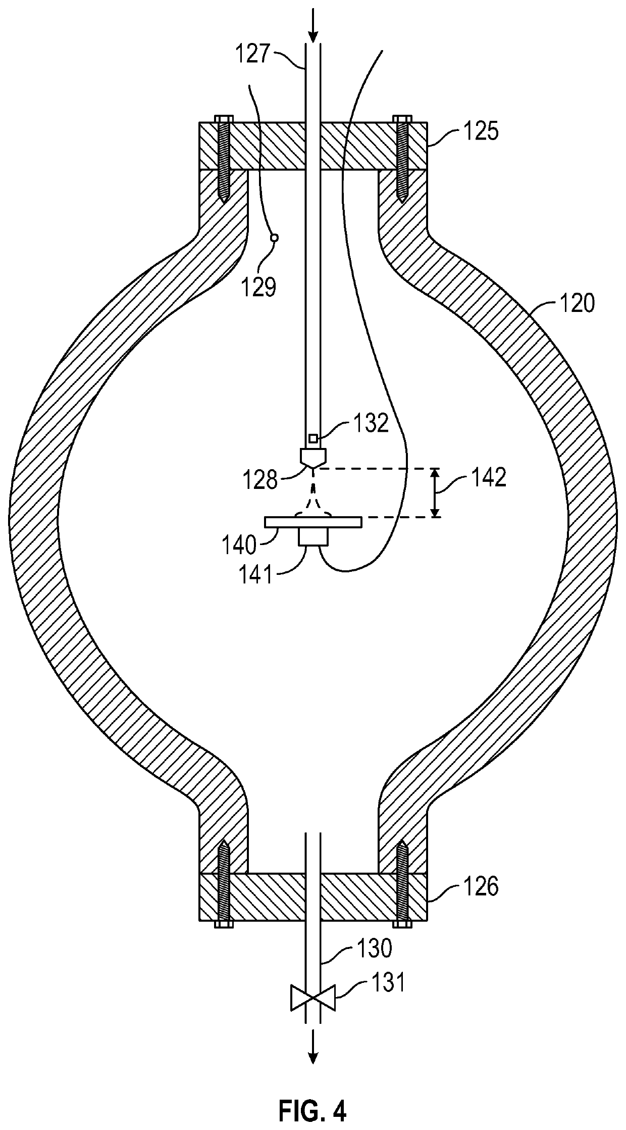
[0076]Referring now to FIG. 4, a number of tests were conducted using a high pressure chamber 120, capable of withstanding internal hydrostatic pressure in excess of 10,000 psi. The chamber was filled with water (to simulate the fluid in the casing and in the well annulus).

[0077]The pressure chamber 120 was fitted with upper and lower end plates 125, 126. Passing through the upper end plate 125 was a conduit 127 terminating in a nozzle 128 inside the pressure chamber 120. Facing the nozzle 128 and spaced from it was a plate 140. The distance between the plate 140 and nozzle 128 can be varied remotely from outside the chamber, by means not shown. The plate was mounted on a force / deflection sensor 141 which was located on the opposite side of the plate to the side facing the nozzle 128.

[0078]A pressure sensor 129, with associated lead passing through the upper end plate 125 to display or monitoring apparatus (not shown), was arranged to detect the ambient hydrostatic pressure in the c...

example 2

[0084]The pressure tank, nozzle and plate arrangement of Example 1 was modelled in computational fluid dynamics (CFD) software and then tests run in the CFD software. The purpose of these tests was principally to compare the results to determine if the CFD testing accurately reflected the physical tests in the pressure tank.

[0085]The CFD modelling in this and other examples below employed software marketed under the trade name “Fluent” by Ansys Inc. Key results from these CFD tests are shown in Table 1 below, side by side with equivalent results from the physical tank test of Example 1. The correlation is good. The term “clearance” in this table refers to the distance between the nozzle tip and the pressure plate.

TABLE 1FlowForce onNozzleRatePlate (lbs)SizeClearance(gpm)TestsCFD 4 / 32″  4.2″2049.249.430113.5111.316″2023.622.03055.148.9 6 / 32″16″3028.922.53738.833.1

example 3

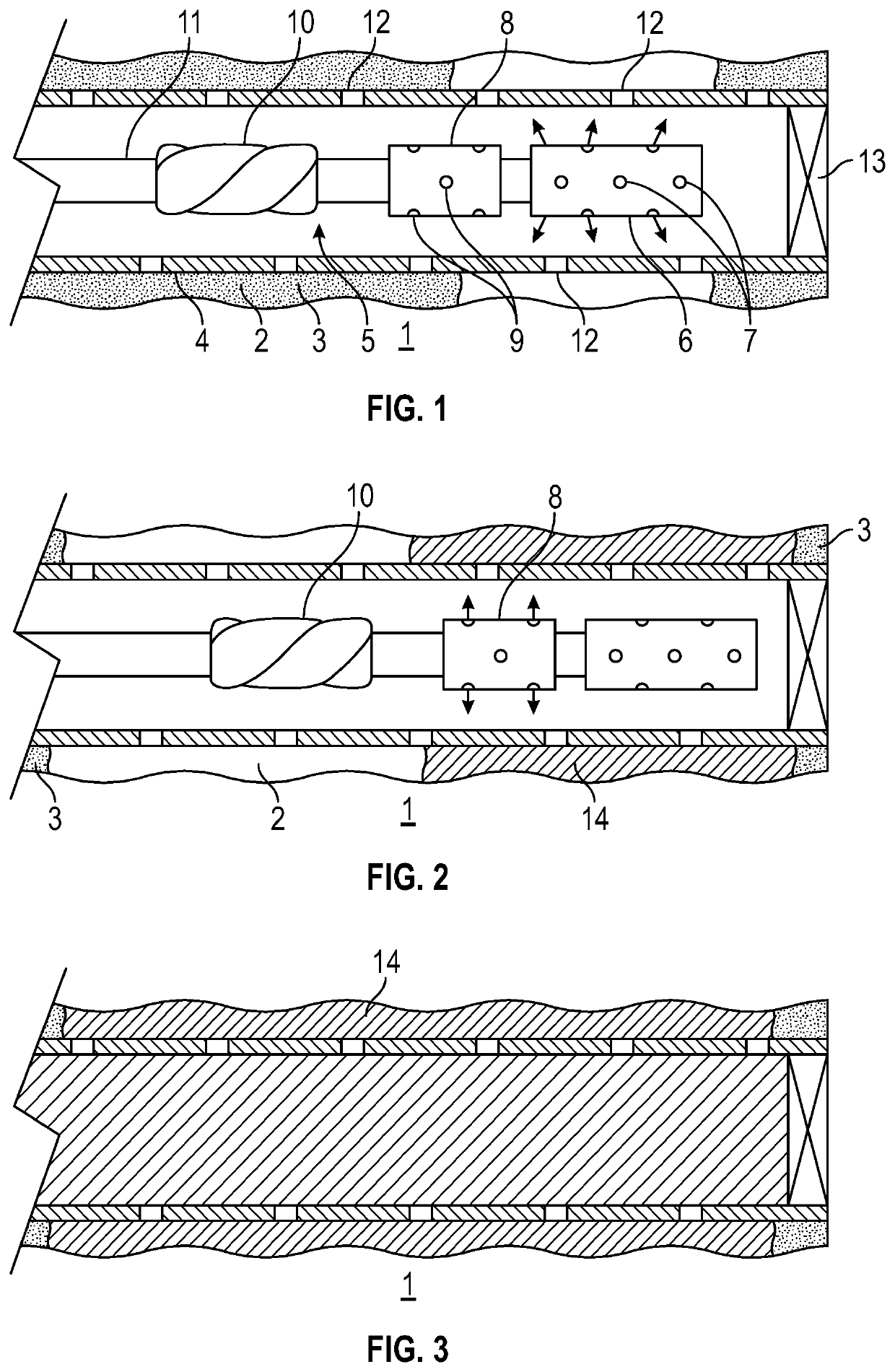
[0086]Further CFD work was then performed using a much more detailed CFD model which included a wash tool with more than one nozzle located within a perforated casing directing jets outwardly into an annulus. One foot long sections of industry standard 9⅝ inch diameter casing were modelled with either 18 or 20 perforations of either 1 inch or 1.4 inch diameter. For this test, the annulus fluid was modelled as a viscous medium including solid debris, similar to the expected contents of a real annulus. Although the content of an annulus can vary widely, the modelled annulus content was considered to be almost a “worst case”, unless the content of the annulus was compacted solid material which would not behave like a fluid at all. In the latter event it would be expected that this compacted volume would become part of the final cemented seal.

[0087]The CFD model was a realizable k-e turbulence model in the Fluent software, using a scalable wall function with appropriate Y+ value to capt...


PUM


Abstract

The invention relates to a method of conducting a perf wash cement (“P/W/C”) abandonment job in an offshore oil or gas well annulus (2), in particular the washing or cementing operation using a rotating head (6, 8) with nozzles (7, 9) dispensing wash fluid or cement at pressure. Certain values of parameters of a washing or cementing job have been found surprisingly to affect the quality of the job, or the degree to which they affect the quality of the job has been unexpected. These include including rotation rate of the tool, the direction of translational movement of the tool, and the volume flow rate and pressure per nozzle of cement or wash fluid (and hence nozzle size).

Description

CROSS-REFERENCE TO RELATED APPLICATIONS[0001]This application is a non-provisional application which claims benefit under 35 USC § 119(e) to U.S. Provisional Application Ser. No. 62 / 713,629 filed Aug. 2, 2018, entitled “BEHIND CASING WASH AND CEMENT” which is incorporated herein in its entirety.STATEMENT REGARDING FEDERALLY SPONSORED RESEARCH[0002]None.FIELD OF THE INVENTION[0003]This invention relates to the process of washing and cementing behind the casing of a well, for example in a so-called perf, wash cement well decommissioning operation.BACKGROUND OF THE INVENTION[0004]In a process for placing cement in the annulus of a well, normally the annulus between casing and wellbore (e.g. in a perf, wash cement well abandonment operation), there are three distinct steps:[0005]Opening the casing (explosive, mechanical, abrasive or melt based perforation)[0006]Washing the annulus between casing and wellbore[0007]Displacing in plugging material (e.g. cement).[0008]There are currently tw...

Claims


Application Information

Patent Timeline
IPC IPC(8): E21B41/00E21B37/00
CPCE21B37/00E21B41/0078E21B37/08E21B33/14
Inventor WATTS, RICKHAAVARDSTEIN, STEINHOVDA, LARSSTEVENS, JAMES C.MUELLER, DANBORLAND, BRETTPHADKE, AMALGONUGUNTLA, PRAVEEN
Owner CONOCOPHILLIPS CO
Why Eureka
Try Eureka