Communication system

a communication system and communication terminal technology, applied in the field of communication systems, can solve problems such as collision risks, and achieve the effects of reducing the latency of communication between the base station device and increasing the power consumption of the communication terminal device, and saving the power consumption required for reception

Inactive Publication Date: 2020-02-06
MITSUBISHI ELECTRIC CORP
View PDF0 Cites 21 Cited by
  • Summary
  • Abstract
  • Description
  • Claims
  • Application Information

AI Technical Summary

Benefits of technology

[0068]A communication system according to the present invention includes a base station device and at least one communication terminal device capable of radio communication with the base station device. The base station device notifies the communication terminal device of information on a next reception timing. The communication terminal device performs reception based on the information on the next reception timing that has been notified from the base station device. Since the communication terminal device can receive the information transmitted from the base station device with the notified reception timing, the power consumption required for the reception can be saved. Since retransmission can be promptly performed when the retransmission is necessary, the latency in the communication between the base station device and the communication terminal device can be reduced. Thus, increase in the power consumption of the communication terminal device, degradation in the communication quality, and reduction in the use efficiency of radio resources can be suppressed.

Problems solved by technology

The RACH involves a collision risk.

Method used


Image

  • Communication system
  • Communication system
  • Communication system

Examples


second embodiment

[0276]The physical control channel to which uplink control information (UCI) is to be mapped is the PUCCH in the LTE. The PUCCH resources are set to each UE. For example, the scheduling request (SR) configuration such as the PUCCH resources for SR and the SR period is set to each UE (see 3GPP TS 36.211 V 14.0.0 (hereinafter referred to as “Reference 3”) and 3GPP TS 36.213 V14.0.0 (hereinafter referred to as “Reference 4”). The RRC signaling is used in these settings (see 3GPP TS 36.331 V14.0.0 (hereinafter referred to as “Reference 5”)).

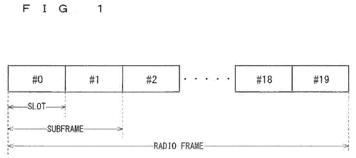
[0277]Multi-beamforming (MBF) requiring the beam sweeping is being studied in the NR. The MBF requiring the beam sweeping requires switching between beams to cover all the coverages. Since one subframe is solely used for transmitting and receiving one beam, the subframe cannot be used for transmitting and receiving the other beams. Thus, the conventional LTE setting method for configuring PUCCH resources for a plurality of UEs in one subframe has a p...

third embodiment

[0583]The second embodiment to the second modification of the second embodiment disclose methods for allocating the PUCCH of each beam to different resources as methods for transmitting and receiving the PUCCH in the MBF requiring the beam sweeping. The third embodiment will disclose another method as the method for transmitting and receiving the PUCCH in the MBF requiring the beam sweeping.

[0584]The cell assigns priorities for receiving the PUCCH to beams. The cell assigns the priorities for receiving the PUCCH to the beams, and receives the PUCCH via the target beam according to the priorities.

[0585]The cell may assign priorities to UEs. The cell may assign priorities to beams via which the UEs communicate, using the priorities of the UEs. For example, the cell assigns priorities to beams in descending order of the priorities among the UEs communicating via the same beam.

[0586]The following (1) to (9) will be disclosed as examples of an indicator for assigning priorities.

[0587](1)...

fourth embodiment

[0643]The second to the third embodiments disclose allocating symbols as the smallest unit of resources to which the PUCCH is allocated. As the number of times the beam sweeping is performed increases, the number of symbols necessary for the PUCCH resources also increases. Thus, configuring the PUCCH resources for many beams within one subframe will cause problems of reduction in the resources for data and decrease in the communication rate. Alternatively, configuring the PUCCH resources for fewer beams within one subframe requires the PUCCH resources over a plurality of subframes, and increases intervals at which the PUCCH resources for each beam are generated. These create a problem of increase in the latency.

[0644]The fourth embodiment will disclose a method for solving such problems.

[0645]A plurality of symbols are configured within one symbol duration, and the PUCCH resources of a plurality of beams are time-division multiplexed. The number of the plurality of symbols to be con...


PUM


Abstract

Provided is a communication system capable of suppressing increase in the power consumption of a communication terminal device, degradation in the communication quality, and reduction in the use efficiency of radio resources. A base station device (gNB) notifies a communication terminal device (UE) of information on the next reception timing. The UE receives, for example, a downlink control signal (902) in a subframe (901). The UE obtains, from the downlink control signal (902), information on a piece of user data (903) in the subframe (901), and the information (904) on the next reception timing. The UE transmits and receives the piece of user data (903) to and from the gNB. The information (904) on the next reception timing indicates a subframe (905) as the next reception timing of the UE. The UE receives a downlink control signal (906) in the subframe (905).

Description

TECHNICAL FIELD[0001]The present invention relates to a communication system in which radio communication is performed between a communication terminal device such as a user equipment device and a base station device.BACKGROUND ART[0002]The 3rd generation partnership project (3GPP), the standard organization regarding the mobile communication system, is studying communication systems referred to as long term evolution (LTE) regarding radio sections and system architecture evolution (SAE) regarding the overall system configuration including a core network and a radio access network, which will be hereinafter collectively referred to as a network as well (for example, see Non-Patent Documents 1 to 5). This communication system is also referred to as 3.9 generation (3.9 G) system.[0003]As the access scheme of the LTE, orthogonal frequency division multiplexing (OFDM) is used in a downlink direction and single carrier frequency division multiple access (SC-FDMA) is used in an uplink dir...

Claims


Application Information

Patent Timeline
Patent Type & Authority Applications(United States)
IPC IPC(8): H04W72/12H04W16/28
CPCH04W52/0209H04W16/28H04W72/1289H04W84/042H04W72/046H04W72/23Y02D30/70
Inventor MOCHIZUKI, MITSURUSHIMODA, TADAHIROFUKUI, NORIYUKIKUSANO, MASAAKI
Owner MITSUBISHI ELECTRIC CORP
Why Eureka
Try Eureka