Light emitting assembly and method thereof

Active Publication Date: 2020-02-13
BAE SYST INFORMATION & ELECTRONICS SYST INTERGRATION INC
View PDF3 Cites 0 Cited by
  • Summary
  • Abstract
  • Description
  • Claims
  • Application Information

AI Technical Summary

Benefits of technology

The patent describes a method and apparatus for producing a stable beam of light from a light emitting device, such as a laser diode, mounted on an optical bench. The method involves using a thermoelectric module to transfer heat from the laser diode to a heat exchanger, while maintaining the optical bench in a stable position for stable light beam parameters. The apparatus includes a mount with a thermoelectric module and a thermal isolator to prevent distortion of the optical bench during temperature changes. The technical effect of this patent is a stable and high-quality laser beam that is not distorted during temperature changes or external environmental influences.

Problems solved by technology

If the optical bench expands or contracts, it may negatively affect the performance of the light emitting device because the deflection of the optical bench may cause the laser diode to move outside of its preferred operating tolerances.
There are certain applications, however, where direct diode light must be utilized and a fiber coupling system is not practical.
Issues continue to exist with light emitting devices that are connected to an optical bench.
Namely, heat transfer from the light emitting device can cause the optical bench to expand or contract which may cause the light emitting device to fail to operate within its preferred operating tolerances.

Method used


Image

  • Light emitting assembly and method thereof
  • Light emitting assembly and method thereof
  • Light emitting assembly and method thereof

Examples


Embodiment Construction

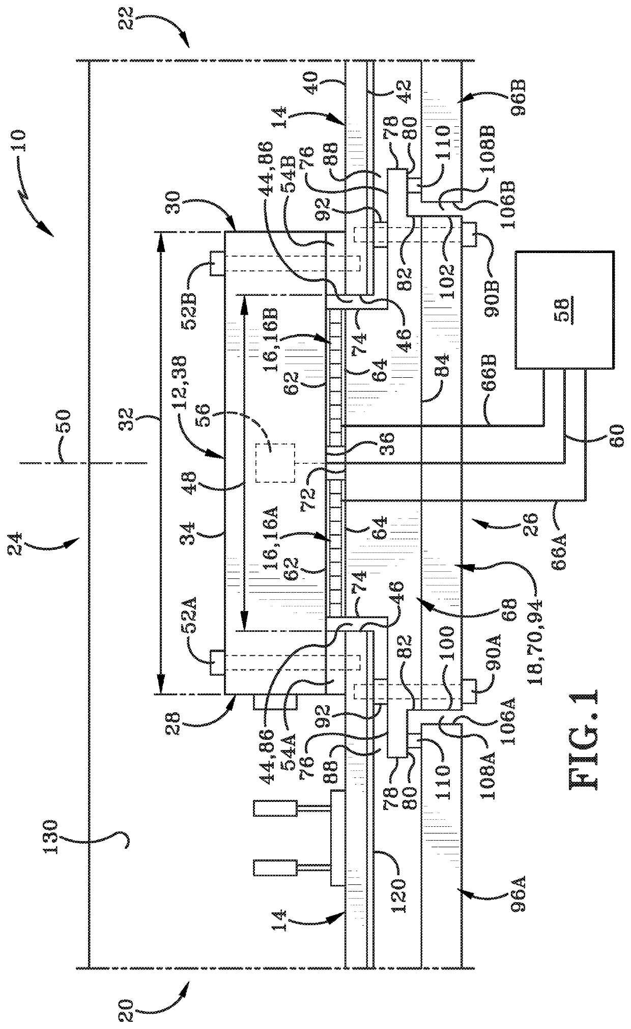
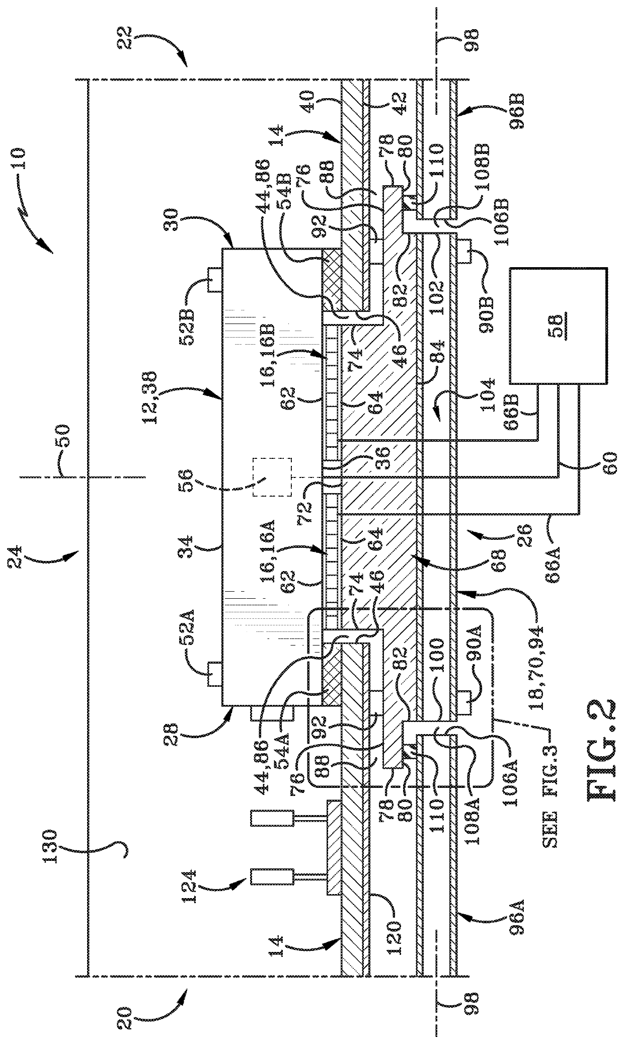
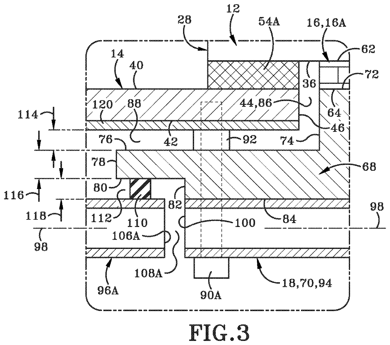
[0018]A light-emitting assembly is depicted throughout the figures generally at 10. The light-emitting assembly 10 includes a light-emitting device 12, an optical bench 14, a thermoelectric module 16, and a heat exchanger 18.

[0019]FIG. 1 depicts the light-emitting assembly 10 as having a first end 20 and a second end 22 defining a longitudinal direction therebetween. Light-emitting assembly 10 further includes a top 24 opposite a bottom 26 defining a vertical direction therebetween. The vertical direction is orthogonal to the longitudinal direction. Light-emitting assembly 10 includes a first side opposite a second side defining a transverse direction therebetween. The transverse direction is orthogonal to the longitudinal direction and orthogonal to the vertical direction.

[0020]With continued reference to FIG. 1, light-emitting device 12 includes a forward or first end 28 opposite a rear or second end 30. A length 32 of the light-emitting device 12 is oriented in the longitudinal d...


PUM


Abstract

A mount connects a light emitting device, such as a laser diode assembly, to an optical bench. The mount may include a thermoelectrical module coupled to a sub-element of a heat exchanger extending through an opening formed in the optical bench. The thermoelectrical module acts as a heat sink to draw heat outwardly from the laser diode and cool the same. The heat sink enables the laser diode to transmit heat thereto such that substantially all of the heat generated by the laser diode sinks to the heat exchanger. As such, the laser diode transfers virtually no heat to the optical bench so the optical bench is free of deflections or distortions resultant from the heat generated during generation of the laser beam.

Description

BACKGROUNDTechnical Field[0001]The present disclosure relates generally to a light emitting assembly, More particularly, the present disclosure relates to a mount for a light emitting device incorporating a heat exchanger. Specifically, the present disclosure relates to thermoelectric modules coupled to a heat exchanger to either warm or cool the light emitting device, which may be a laser.Background Information[0002]Light emitting devices, such as laser diodes, typically operate within a narrow set of tolerances. The tolerances relate to a temperature operating range and a narrow set of deflection angles. Laser diodes are often mounted to an optical bench. Laser diodes emit heat during the generation of a laser beam. Due to the direct mounting of the laser diode to the optical bench, some heat generated by the diode may be transferred to the optical bench. The heat transfer from the laser diode to the optical bench may occur by conduction, convection, radiation, or another type of ...

Claims


Application Information

Patent Timeline
IPC IPC(8): H01S5/024H01S5/022G02B6/42H01S5/0238
CPCG02B6/4225G02B6/4204H01S5/02415H01S5/02268H01S5/02252G02B6/4271H01S5/0222H01S5/3401H01S5/02453H01S5/02423H01S5/0236H01S5/02326H01S5/02365H01S5/0238
Inventor BELLEY, DAVID B.SPAHR, ERIK J.
Owner BAE SYST INFORMATION & ELECTRONICS SYST INTERGRATION INC
Why Eureka
Try Eureka