Transducer and method for manufacturing same

a transducer and manufacturing method technology, applied in the direction of mechanical vibration separation, pedestrian/occupant safety arrangement, vehicular safety arrangement, etc., can solve the problems of reducing the efficiency of the electrostatic capacitance, affecting the electrostatic capacitance of the intended electrostatic capacitance, and the remaining constituents of the organic solvent, so as to reduce the voc discharge

Active Publication Date: 2020-02-13
SUMITOMO RIKO CO LTD
View PDF4 Cites 3 Cited by
  • Summary
  • Abstract
  • Description
  • Claims
  • Application Information

AI Technical Summary

Benefits of technology

[0019]An aspect of the disclosure is to provide a transducer that can be manufactured without using a volatilization-type adhesive and an organic solvent and a method for manufacturing the same. Also, another aspect of the disclosure is to provide a transducer with flexibility and stretchability and a method for manufacturing the same.

Problems solved by technology

However, manufacturing costs significantly increase in a case in which sewing is performed on the steering wheel.
There is concern that the remaining constituents of the organic solvent may affect the electrostatic capacitance.
As a result, there is concern that an intended electrostatic capacitance may not be able to be obtained due to the influence of the remaining constituents of the organic solvent.
If the transducer does not have flexibility and stretchability, it may not be possible to neatly attach the transducer to an attachment target with a freely curved surface.
Further, there is a concern that in the case in which a volatilization-type adhesive and an organic solvent are used as described above, constituents of the volatilization-type adhesive and the organic solvent may affect the flexibility and stretchability of the transducer.
Also, utilization of a support frame that is a member separate from a sensor or an actuator for the purpose of attaching the sensor or the actuator to an attachment target (a core body of a steering wheel or the like) leads to an increase in costs.

Method used


Image

  • Transducer and method for manufacturing same
  • Transducer and method for manufacturing same
  • Transducer and method for manufacturing same

Examples


first example

3. First Example

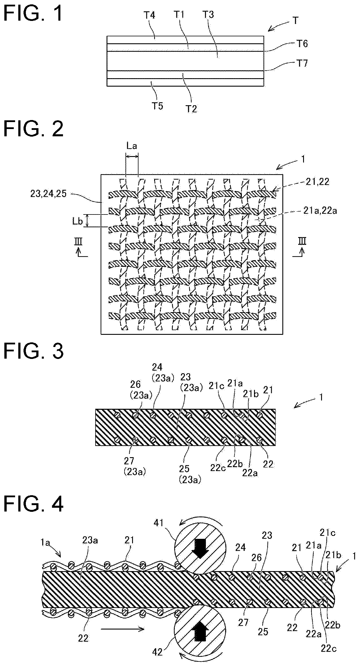
[0093]A transducer 1 in the first example will be described with reference to FIGS. 2 to 4. As illustrated in FIGS. 2 and 3, the transducer 1 includes an electrostatic sheet including a first electrode sheet 21, a second electrode sheet 22, a dielectric layer 23, a first protective layer 24, and a second protective layer 25. Also, the transducer 1 in the first example can have a configuration in which the transducer 1 includes an electrostatic sheet that includes the first electrode sheet 21, the dielectric layer 23, and the first protective layer 24 without including the second electrode sheet 22 and the second protective layer 25, and also, the transducer 1 includes a non-deformable conductive member (not illustrated) corresponding to the second electrode layer T2 (illustrated in FIG. 1).

[0094]The first electrode sheet 21 and the second electrode sheet 22 are conductive cloths. The first electrode sheet 21 and the second electrode sheet 22 have conductivity, flexib...

second example

4. Second Example

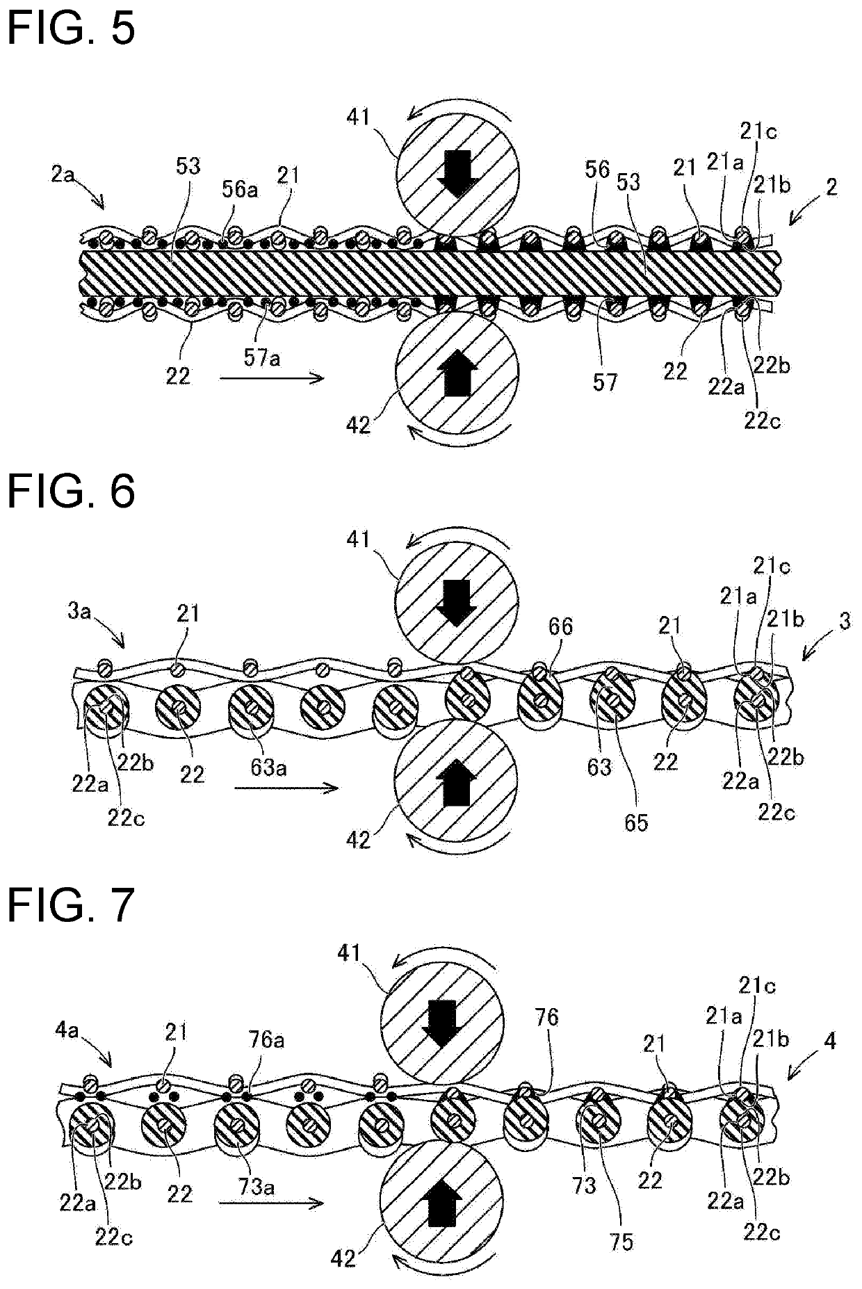
[0118]A transducer 2 and a method for manufacturing the transducer 2 in the second example will be described with reference to FIG. 5. The same reference numerals will be used to denote components the same as those in the first example, and detailed description thereof will be omitted.

[0119]As illustrated on the left side in FIG. 5, (a) the first electrode sheet 21, (b) the second electrode sheet 22, (c) a dielectric layer 53, (d) a first fusion-bonding material 56a, and (e) a second fusion-bonding material 57a are prepared for a material 2a of the transducer 2. The dielectric layer 53 is formed from a non-thermoplastic material. In particular, the dielectric layer 53 is formed from a non-thermoplastic material elastomer in this example. Further, a foaming material of the non-thermoplastic material elastomer is used for the dielectric layer 53. That is, the dielectric layer 53 has holes that establish communication in the normal line direction of the sheet, that is,...

third example

5. Third Example

[0131]A transducer 3 and a method for manufacturing the transducer 3 in the third example will be described with reference to FIG. 6. The same reference numerals will be used to denote components the same as those in the first example, and detailed description thereof will be omitted.

[0132]As illustrated on the left side in FIG. 6, (a) the first electrode sheet 21 and (b) a member in which the second electrode sheet 22 and a dielectric material 63a are integrated are prepared as a material 3a of the transducer 3. Here, the dielectric material 63a is formed from a thermoplastic elastomer similar to the dielectric material 23a in the first example.

[0133]The dielectric material 63a is integrally and mechanically engaged by being caused to the entire surface of the conductive fiber of the second electrode sheet 22 through dipping, spraying, coating, or the like. Therefore, the dielectric material 63a is caused to adhere to all the second inner circumferential surfaces of...


PUM

PropertyMeasurementUnit
opening lengthaaaaaaaaaa
areaaaaaaaaaaa
opening lengthaaaaaaaaaa

Abstract

Provided is a transducer that can be manufactured without using a volatile adhesive or an organic solvent. A transducer is provided with: a first electrode sheet provided with a plurality of first through-holes; a dielectric layer, of which a first surface is disposed on the first-electrode-sheet side; and a first fusion-bonding layer formed from a fusion-bonding material, the first fusion-bonding layer joining together, by fusion bonding of the fusion-bonding material, a boundary region between a body portion of the dielectric layer and a first inner surface of the first electrode sheet and a boundary region between the body portion of the dielectric layer and a first inner circumferential surface of at least some of the plurality of first through-holes.

Description

CROSS-REFERENCE TO RELATED APPLICATION[0001]The present application is a continuation of PCT / JP2018 / 036242, filed on Sep. 28, 2018, and is related to and claims priority from Japanese patent application no. 2017-191447, filed on Sep. 29, 2017, Japanese patent application no. 2017-251418, filed on Dec. 27, 2017, Japanese patent application no. 2018-124273, filed on Jun. 29, 2018, and Japanese patent application no. 2018-170510, filed on Sep. 12, 2018. The entire contents of the aforementioned application are hereby incorporated by reference herein.BACKGROUNDTechnical Field[0002]The present disclosure relates to a transducer and a method for manufacturing the same.Description of Related Art[0003]Patent Literature 1 discloses a piezoelectric element in which an electrode in the form of a porous sheet is buried in a polymer piezoelectric body. The piezoelectric element is manufactured by treating a surface of a polymer piezoelectric film or sheet with an organic solvent such as acetone ...

Claims


Application Information

Patent Timeline
Patent Type & Authority Applications(United States)
IPC IPC(8): H04R19/00H01L41/193H01L41/047B60R21/015B62D1/04B62D1/06
CPCH01L41/0477B62D1/046H01L41/193B60R21/01552H04R19/00B62D1/065H04R31/00B06B1/0292B06B2201/51H10N30/87H10N30/877H10N30/00H10N30/857H10N30/06
Inventor NAKANO, KATSUHIKONASU, MASAKIHASEGAWA, KOICHITAHARA, SHINYA
Owner SUMITOMO RIKO CO LTD
Why Eureka
Try Eureka