Coanda effect bearing cooler

Active Publication Date: 2020-02-20
FLOWSERVE MANAGEMENT CO
View PDF0 Cites 0 Cited by
  • Summary
  • Abstract
  • Description
  • Claims
  • Application Information

AI Technical Summary

Benefits of technology

The present invention provides a cooling system for a rotating device using a fan blade and a Coanda surface. The fan blade is smaller in diameter than the bearing housing and directs a flow of air radially outward and tangential to the end surface of the housing. The Coanda surface is a smoothly curved transition of the housing end surface to axial alignment with the side of the housing. The system eliminates the need for ducting, reducing the bulk and cost of the cooling system and improving cooling efficiency. The fan blade is made from a lightweight, non-metallic material, reducing the likelihood of fan-induced rotor imbalance and improving rotor stability.

Problems solved by technology

While there are many styles of bearings that can support a rotating shaft, with varying degrees of complexity and cost, it is unavoidable that bearings will generate heat in proportion to the amount of load that they are carrying.
However, it can be expensive and excessively bulky to provide a completely independent fan and duct system for air cooling the bearings.
While this approach is effective in cooling the bearings, it is energetically inefficient, due to frictional losses between the flowing air and the ductwork and the considerable amount of “wasted” airflow that is generated by the fan but does not contribute significantly to cooling of the bearings.
Also, the large size of the fan blades, which are typically made of metal so as to be sufficiently rigid, places a significant additional load onto the rotating shaft, and can lead to increased heating of the bearings, due to rotor imbalances and other rotor dynamic issues.
In addition, the ductwork that surrounds the bearing housings adds considerable bulk to the overall system.
However, this redirection of the air flow by the ductwork 108 leads to additional energy loss, which must be compensated by drawing more energy from the rotating shaft 104.

Method used


Image

  • Coanda effect bearing cooler
  • Coanda effect bearing cooler
  • Coanda effect bearing cooler

Examples


Embodiment Construction

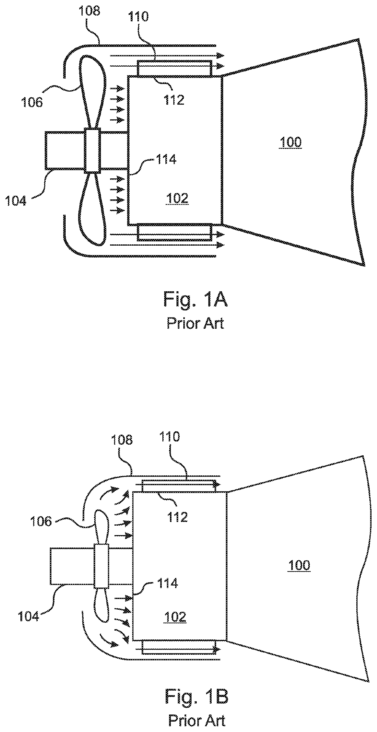
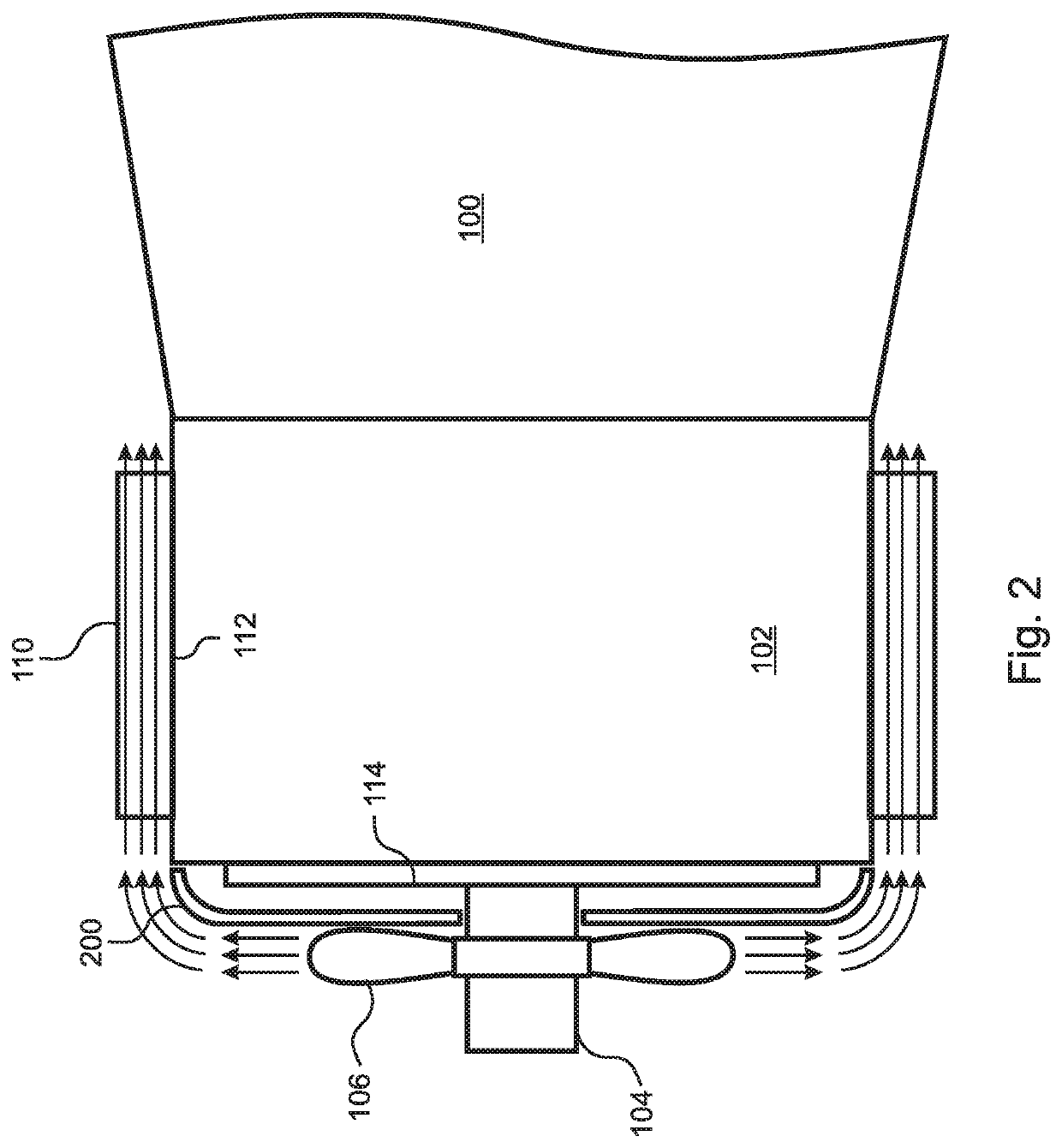
[0046]The present invention is a compact and energetically efficient apparatus for applying cooling air to a bearing housing of a rotating shaft device. The cooling apparatus does not add significant load to the rotating shaft, and requires only a minimal increase in system bulk.

[0047]According to the present invention, a fan blade that is smaller in diameter than the bearing housing is mounted on the extending end of the rotary shaft adjacent to a Coanda surface, and is configured to direct a flow of air radially outward and tangential to the Coanda surface. The center of the Coanda end surface is perpendicular to the rotating shaft, while a periphery of the Coanda end surface makes a smoothly curved transition to axial alignment with the side of the housing.

[0048]Instead of relying on ductwork, the disclosed apparatus makes use of the Coanda effect to redirect the airflow from radial to axial, and to maintain the airflow in close proximity to the housing. In embodiments, the Coand...


PUM


Abstract

A compact, energy efficient air cooling system for a rotating shaft bearing module includes a Coanda surface having a periphery that smoothly curves from a radial center to axial alignment with a side of the module. A fan blade mounted on the shaft directs an airflow radially parallel and adjacent to the Coanda surface, causing the airflow to be bent by the Coanda effect from radial to axial, and to be directed along the side of the housing. Embodiments that can be applied to existing housings include a Coanda panel adjacent to the housing end face. A double suction fan blade can draw both external air and air from between the panel and the housing. In other embodiments the housing end face itself is a Coanda surface. A fan cover can have an inwardly curved periphery that forms a reduced gap or nozzle with the Coanda surface.

Description

RELATED APPLICATIONS[0001]This application claims the benefit of U.S. Provisional Application No. 62 / 462,040, filed Feb. 22, 2017, which is herein incorporated by reference in its entirety for all purposes.FIELD OF THE INVENTION[0002]The invention relates to rotating shaft devices, and more particularly, to apparatus for cooling bearing housings and other modules from which rotating shafts extend.BACKGROUND OF THE INVENTION[0003]Centrifugal pumps and other rotating shaft devices generally include radial and / or axial bearings that support the weight of the rotating shaft and also absorb radial and axial forces and vibrations that arise from a number of different sources, including hydraulic and mechanical sources. The bearings are typically surrounded by bearing housings and are located on either end of the shaft. In the case of centrifugal pumps, the bearings are typically external to the pumped fluid.[0004]While there are many styles of bearings that can support a rotating shaft, w...

Claims


Application Information

Patent Timeline
IPC IPC(8): F16C37/00F04D29/54
CPCF04D29/547F05D2260/60F16C37/00F04D29/441F04D25/08F16C2360/46H02K9/14H02K5/18H02K5/207
Inventor JUDGE, SCOTT C.KOEHLER, ANDREW TODDSCHAPPERT, STEPHEN R.
Owner FLOWSERVE MANAGEMENT CO
Why Eureka
Try Eureka