
Robot controller and method of controlling robot

a robot controller and robot technology, applied in the direction of program control, total factory control, instruments, etc., can solve the problems of reducing productivity, not sufficiently studying the timing of the component replacement when a plurality of robots is predicted, and not sufficiently studying the timing of the component replacemen

Pending Publication Date: 2020-02-27
SEIKO EPSON CORP
View PDF4 Cites 1 Cited by
  • Summary
  • Abstract
  • Description
  • Claims
  • Application Information

AI Technical Summary

Benefits of technology

The present invention is a controller that can manage multiple robots. The controller includes a section that predicts when each robot will fail and a section that adjusts the workload of each robot accordingly to ensure they operate until a common maintenance time. This results in more efficient use of the robots and reduces downtime for maintenance.

Problems solved by technology

However, in JP-A-2017-102554, the timing of the component replacement when failure is predicted for a plurality of robots is not sufficiently studied.
Therefore, when failure of the plurality of the robots is predicted, a maintenance time at which a component is replaced or the like varies from robot to robot, which may lower productivity.

Method used


Image

  • Robot controller and method of controlling robot
  • Robot controller and method of controlling robot
  • Robot controller and method of controlling robot

Examples


first embodiment

A. First Embodiment

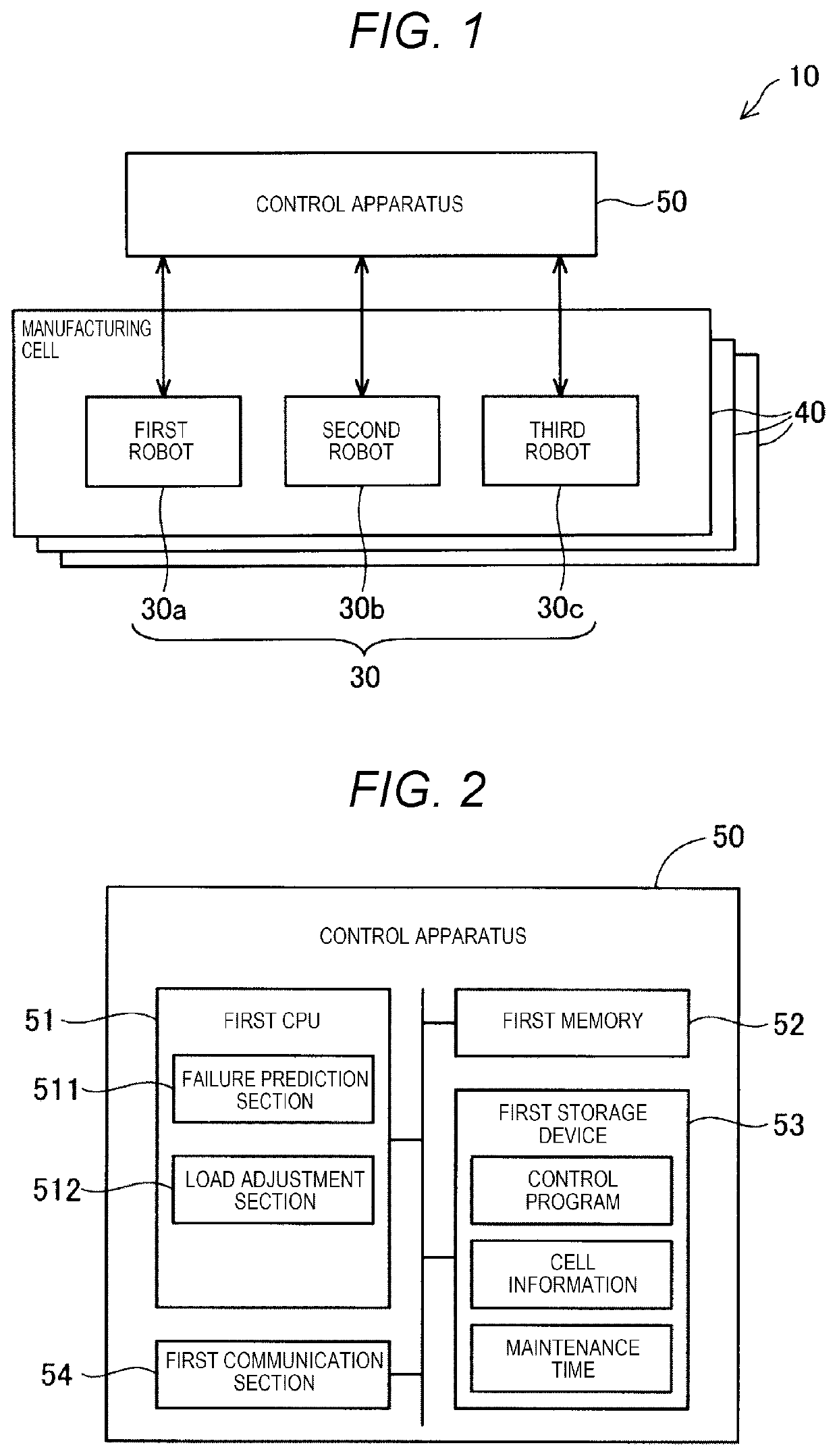
[0013]FIG. 1 is a diagram illustrating a schematic configuration of a robot system 10 in an embodiment. The robot system 10 includes a plurality of manufacturing cells 40 and a controller 50. Each of the manufacturing cells 40 is a set of manufacturing facility including a plurality of robots 30. Respective manufacturing cells 40 are disposed at positions distant from each other in a factory. In the embodiment, each of the manufacturing cells 40 includes a first robot 30a, a second robot 30b, and a third robot 30c. In the following, when these robots are described without distinction, they will be referred to as “robots 30”. In the embodiment, the respective robots 30 in the manufacturing cell 40 individually produce and process objects. The number of the robots 30 provided in each of the manufacturing cells 40 is arbitrary. The controller 50 may be disposed in the factory where the manufacturing cells 40 are disposed or may be disposed at a position distant from ...


PUM


Abstract

A controller for controlling a plurality of robots includes a failure prediction section configured to predict a failure time for each of the robots; and a load adjustment section configured to perform adjustment of a work load of each of the robots according to each of the predicted failure times, so that each of the robots operates until a maintenance time determined in common to each of the robots.

Description

[0001]The present application is based on, and claims priority from JP Application Serial Number 2018-155943, filed Aug. 23, 2018, the disclosure of which is hereby incorporated by reference herein in its entirety.BACKGROUND1. Technical Field[0002]The present disclosure relates to a robot controller and a method of controlling a robot.2. Related Art[0003]JP-A-2017-102554 discloses a technique related to a controller that controls a robot and, for example, estimating a failure time of a component constituting the robot from an operating situation of the robot. In JP-A-2017-102554, a failure time of the robot is delayed by stopping work of a part of the robot or reducing an operation speed, so that an estimated failure time is not earlier than a predetermined replacement time of a component.[0004]However, in JP-A-2017-102554, the timing of the component replacement when failure is predicted for a plurality of robots is not sufficiently studied. Therefore, when failure of the plurality...

Claims


Application Information

Patent Timeline
Patent Type & Authority Applications(United States)
IPC IPC(8): B25J9/16G05B19/4063G05B19/4065G05B19/418
CPCB25J9/1674G05B2219/31356G05B19/4065G05B2219/32229G05B2219/32371G05B19/418G05B2219/39G05B19/4063G05B2219/32257G05B19/41865Y02P90/02Y02P90/80
Inventor KANAZAWA, KANA
Owner SEIKO EPSON CORP
Learn More