
Method for creating gridded reference graphics

a reference graphics and reference graphics technology, applied in the field of creating reference graphics, can solve the problems of complex and cumbersome software for creating gis images, orthophotomaps and grgs, and the complexity and cumbersomeness of annotating digital gis source images, so as to reduce the complexity and difficulty of creating, quick and convenient creation of grgs, easy import and manipulation

Inactive Publication Date: 2020-02-27
KILLEEN ETHAN P
View PDF1 Cites 3 Cited by
  • Summary
  • Abstract
  • Description
  • Claims
  • Application Information

AI Technical Summary

Benefits of technology

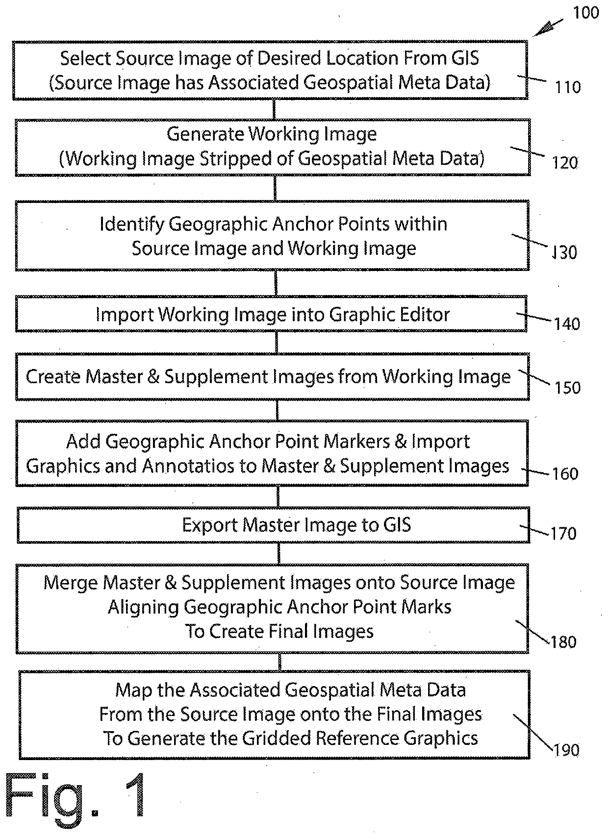
The present invention proposes a method for creating GRGs (Geospatial Reference Grids) for use in geospatial information systems and geospatial intelligence software solutions. The method involves creating a high resolution raster or "dumb" working image from a more complicated and sizable GIS source image, which can be easily imported and manipulated within conventional graphic editing and creation software, such as Adobe Illustrator or Photoshop. The resulting master image can be exported back into the GIS and the geospatial metadata from the source image mapped into the master image creating the GRG having full functionality within the GIS. The method simplifies the process of creating, editing, and manipulating large GIS image files within conventional GIS platforms and provides more tools and flexibility in creating enhancement graphics and annotations for GRGs.

Problems solved by technology

While digital photogrammetry software programs are now commercially available, such as the software for creating GIS images, orthophotomaps and GRGs remain complex and cumbersome.
Much of the complexity and cumbersomeness is found in annotating the digital GIS source images.
The size of these digital GIS image files slows rendering and distribution.
In addition, such software lacks many of the illustration tools and conventions to quickly and adequately annotate and enhance the GIS source images to create GRGs practical for use in the field.

Method used


Image

  • Method for creating gridded reference graphics
  • Method for creating gridded reference graphics
  • Method for creating gridded reference graphics

Examples


Embodiment Construction

[0021]In the following detailed description of the preferred embodiments, reference is made to the accompanying drawings that form a part hereof, and in which is shown by way of illustration specific preferred embodiments in which the invention may be practiced. These embodiments are described in sufficient detail to enable those skilled in the art to practice the invention, and it is understood that other embodiments may be utilized and that logical, structural, mechanical, electrical, and chemical changes may be made without departing from the spirit or scope of the invention. To avoid detail not necessary to enable those skilled in the art to practice the invention, the description may omit certain information known to those skilled in the art. The following detailed description is, therefore, not to be taken in a limiting sense, and the scope of the present invention is defined only by the appended claims.

[0022]The following is a glossary of terms as used in the description of t...


PUM


Abstract

A method for creating GRG for use in geospatial information systems and geospatial intelligence software solutions. The method includes creating a high resolution raster working image from a more complicated and sizable GIS source image. The working image is stripped of the embedded or associated meta data and can be easily imported and manipulated within conventional graphic editing and creation software. Geographic anchor points are selected and marked on separate graphic layers of the working image, along with additional graphics and annotations, and saved as a master image. The master image is exported back into the GIS platform using the anchor point markers to align the overlying master images with the original source image. Meta data from the source image is re-associated with the master image and saved as a final image.

Description

[0001]This invention relates to a method for creating gridded reference graphics, and in particular, a method for annotated orthophotomaps for use as gridded reference graphics in geospatial intelligence software solutions.BACKGROUND AND SUMMARY OF THE INVENTION[0002]BAE Systems Information and Electronic Systems Integration, Inc. of Nashua, N.H. (“BAE”) has developed advanced geospatial intelligence software solutions for visual, real-time coordination and identification of personnel within given locations within a geographic information system (“GIS”). BAE markets this software solution as SOCET SET® and SOCET GXP®, which provides coordinating location information using specialized orthophotomaps of specific locations. These specialized orthophotomaps are annotated with a grid overlay created using a method disclosed in U.S. Pat. No. 9,830,726 (“Deitrich”). Using the patented method, a grid is digitally imposed onto an orthorectified source GIS image of a location from satellite a...

Claims


Application Information

Patent Timeline
IPC IPC(8): G06T11/60G06T7/73G06T3/00
CPCG06T2207/30181G06T7/73G06T2207/20221G06T2207/10032G06T3/0068G06T11/60G01C11/00G06T3/14
Inventor KILLEEN, ETHAN P.
Owner KILLEEN ETHAN P
Learn More