Ejector for a fuel cell system and fuel cell system

a fuel cell and ejector technology, applied in the field of ejectors for fuel cell systems and fuel cell systems, can solve the problems of inability to adjust the operating state of a fuel cell, and the inability to complete the reaction of all the supplied fuel in the fuel cell stack, so as to reduce the flow cross-section of the membrane, reduce the flow cross-section, and design the effect of the ejector

Active Publication Date: 2020-02-27
AUDI AG
View PDF0 Cites 1 Cited by
  • Summary
  • Abstract
  • Description
  • Claims
  • Application Information

AI Technical Summary

Benefits of technology

[0009]This has the advantage that reducing the flow cross-section of the drive nozzle due to the axial movement of the needle simultaneously results in a reduction in the flow cross-section of the mixing tube. Conversely, an enlargement of the flow cross-section of the drive nozzle is observed when the flow cross-section of the mixing tube increases. At low loads, the mixing tube can thus be reduced in its flow cross-section, whereby lower fuel mass flows are also present. Here, larger mass flows are required at high loads, as a result of which larger flow cross-sections are also required. With the proposed embodiment of the ejector, its recirculation capability can be increased, wherein the recirculation of the anode gas can be ensured solely by the ejector and without the use of further components. In this way, for example, a recirculation blower can be dispensed with in the anode circuit, or such a recirculation blower can be designed to be smaller in terms of size and power.
[0017]If the movement of the needle is not to be applied at a ratio of one to one to the movement of the membrane, it has proven to be advantageous if the coupling mechanism includes a transmission gear designed to transfer the axial movement of the needle at a predetermined gear ratio to the movement of the membrane.

Problems solved by technology

Since the anode reaction is usually operated with superstoichiometric metering of the fuel, there is no complete reaction of all of the supplied fuel in the fuel cell stack.
However, ejectors or jet pumps usually have a fixed geometry so that adjustments to the operating state of a fuel cell are not possible.

Method used


Image

  • Ejector for a fuel cell system and fuel cell system
  • Ejector for a fuel cell system and fuel cell system
  • Ejector for a fuel cell system and fuel cell system

Examples


Embodiment Construction

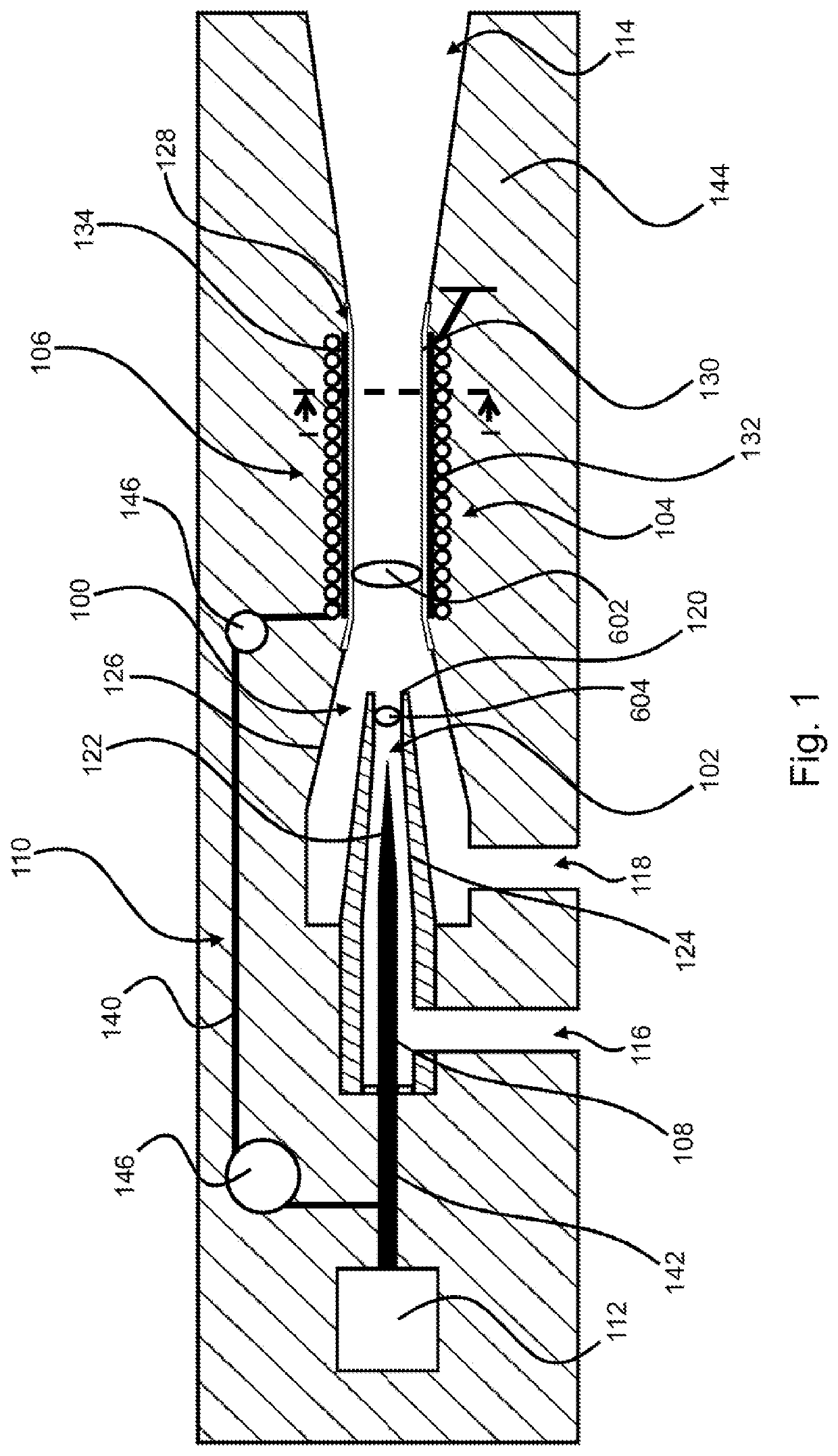
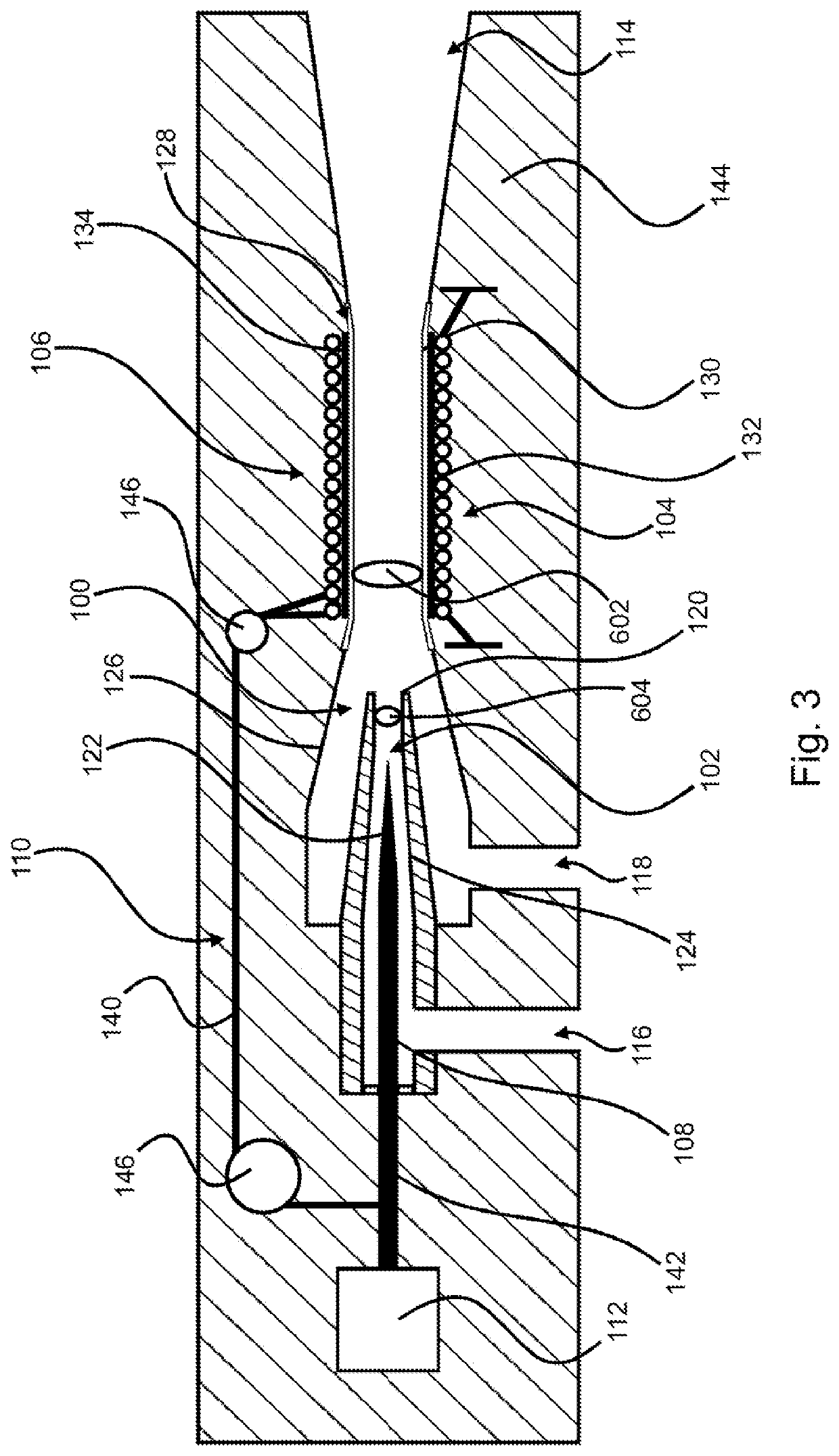
[0040]Various ejectors are described in the figures, wherein the same components are provided with the same reference signs. All ejectors have a suction nozzle 100, a drive nozzle 102 and a mixing tube 104. The ejectors shown also have a diffuser 114 connected to the mixing tube 106. The drive nozzle 102 can be fluidically connected via a port 116 to a fuel storage (not shown in detail) so that through the port 116, fresh fuel can be fed into the mixing tube 104 via the drive nozzle 102. The suction nozzle 100, on the other hand, has a port 118, through which the recirculated fuel that was not consumed in a fuel cell stack (not shown in detail) is introduced or sucked in.

[0041]A needle 108 having a needle tip 122 tapering conically in the direction of the nozzle opening 120 of the drive nozzle 102 is arranged inside the drive nozzle 102, in particular concentrically thereto. Moreover, the drive nozzle 102 itself is designed with a nozzle section 124 tapering in the direction of the ...


PUM

PropertyMeasurementUnit
restoring forceaaaaaaaaaa
dimensionally stable stiffeningaaaaaaaaaa
pressureaaaaaaaaaa

Abstract

An ejector with a suction nozzle is disclosed, with a drive nozzle and with a mixing tube, to which is assigned an adjustment device for the at least region-wise adjustment of a flow cross-section of the mixing tube. Inside the drive nozzle, an axially movable needle which is designed to adjust a flow cross-section of the drive nozzle is arranged and a coupling mechanism is provided which connects the adjustment device to the needle or to an actuator actuating the needle in such a way that the adjustment device adjusts or changes the flow cross-section of the mixing tube as a function of an axial needle movement. A fuel cell system with such an ejector is also disclosed.

Description

BACKGROUNDTechnical Field[0001]Embodiments of the invention relate to an ejector, in particular for an anode circuit of a fuel cell system, comprising a suction nozzle, a drive nozzle and a mixing tube.[0002]An adjustment device is assigned to the mixing tube for the at least region-wise adjustment of a flow cross-section of the mixing tube. Embodiments of the invention also relate to a fuel cell system having a fuel cell stack which is integrated into an anode circuit into which an ejector is fluidically coupled.Description of the Related Art[0003]Fuel cells use the chemical conversion of a fuel with oxygen into water in order to generate electrical energy. For this purpose, fuel cells contain as a core component what is known as the membrane electrode assembly (MEA), which is a combination of a proton-conducting membrane and in each case one electrode (anode and cathode) arranged on each of the two sides of the membrane. In addition, gas diffusion layers (GDL) can be arranged on b...

Claims


Application Information

Patent Timeline
Patent Type & Authority Applications(United States)
IPC IPC(8): H01M8/04089F04F5/20F04F5/44
CPCH01M8/04097F04F5/44F04F5/20H01M8/04201F04F5/16F04F5/461F04F5/48Y02E60/50F04F5/50
Inventor LUCAS, CHRISTIAN
Owner AUDI AG
Why Eureka
Try Eureka