Machining environment measurement device

a measurement device and machining environment technology, applied in the direction of process control, process control, instruments, etc., can solve the problems of adversely affecting the machined surface, defect in the machined surface, and defect in the machined surface, and achieve the effect of high quality and rapid identification

Active Publication Date: 2020-03-05
FANUC LTD
View PDF0 Cites 2 Cited by
  • Summary
  • Abstract
  • Description
  • Claims
  • Application Information

AI Technical Summary

Benefits of technology

[0010]According to the present disclosure, even when a machining process is not actually performed, whether or not the environment is a suitable one where a machine performs machining suited to the purpose of machining (e.g., high quality machining) can be readily confirmed. If a defect in a machined surface suddenly occurs, it is made possible to determine whether or not the defect at issue is caused by the environment (vibration) or any other factor (chips or mistake by an operator). Also, when a defect in a machined surface occurs in a case where a plurality of cutting machines are used in different installation environments, it is made possible to quickly identify the difference between the installation environments of the respective cutting machines. Further, the display of the scores makes it possible to determine the machining capability in accordance with the content of the machining process.

Problems solved by technology

In high quality machining, for example, when the vibration of the spindle increases due to a defect of the spindle caused by collision, a defect in a machined surface occurs.
Also, when vibration of a mist collector which is installed as a peripheral device and a vibration of a fan for cooling are transmitted to the machine tool, they may adversely affect the machined surface.
Specifically, a defect in a machined surface occurs.
In addition, if the load resistance of the floor on which the machine tool is installed is not sufficient, then a defect in a machined surface occurs under various influences including the vibration during acceleration and deceleration and vibration originating from an adjacent machine tool.
When a defect in a machined surface occurs, the current mass production process is halted.
Also, in order to determine from the result of measurement a phenomenon that causes a defect in the machining process, analysis is performed using external devices such as a personal computer and spending a large amount of time.
Accordingly, the costs associated therewith will be large.

Method used


Image

  • Machining environment measurement device
  • Machining environment measurement device
  • Machining environment measurement device

Examples


first embodiment

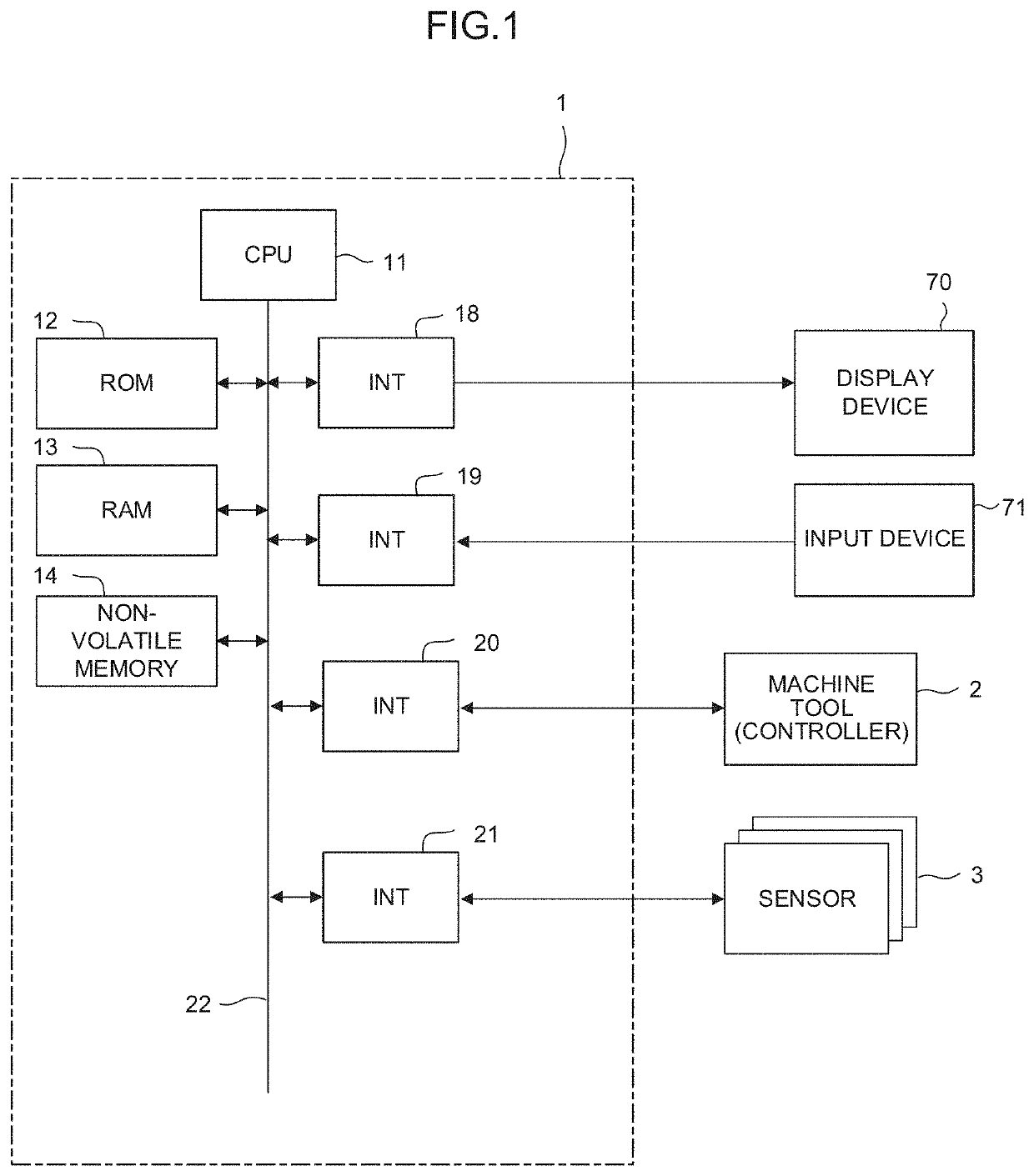
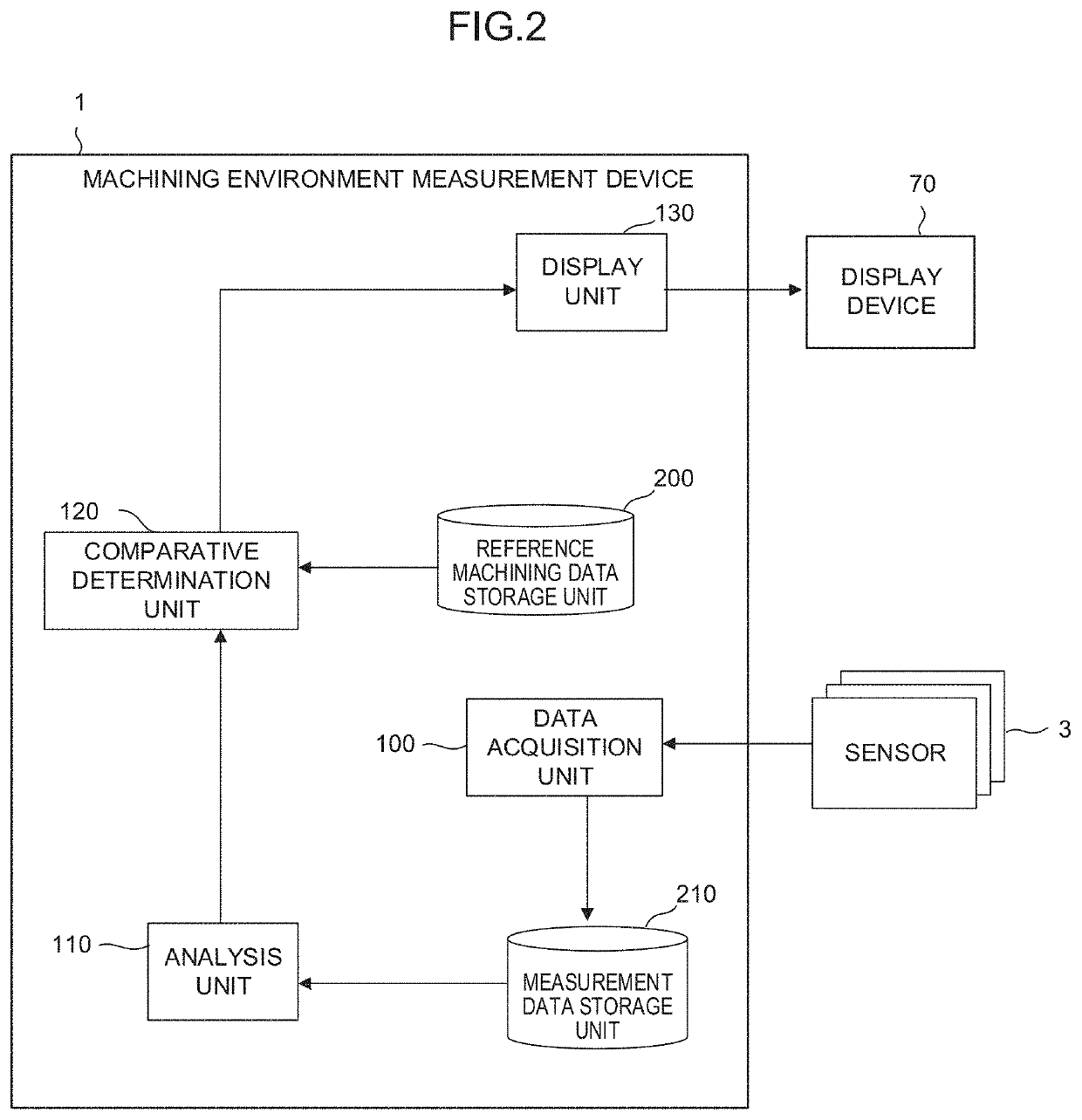
[0027]FIG. 2 is a schematic functional block diagram of the machining environment measurement device 1 according to the The functions of the functional blocks illustrated in FIG. 2 are implemented by the CPU 11 provided in the machining environment measurement device 1 illustrated in FIG. 1, where the CPU 11 executes the system program(s) and controls the operations of the individual units of the machining environment measurement device 1.

[0028]The machining environment measurement device 1 of this embodiment includes a data acquisition unit 100, an analysis unit 110, a comparative determination unit 120, and a display unit 130. Also, a reference machining data storage unit 200 is ensured in the non-volatile memory 14. Reference machining data associated with vibration and the like detected during execution of high quality machining is stored in advance in the reference machining data storage unit 200. The reference machining data serves as a criterion for evaluation of a machining...

second embodiment

[0045]FIG. 10 is a schematic functional block diagram of a machining environment measurement device 1 according to the present disclosure. The individual functional blocks illustrated in FIG. 10 are implemented by the CPU 11 provided in the machining environment measurement device 1 illustrated in FIG. 1 executing the system program and controlling the operations of the individual units of the machining environment measurement device 1.

[0046]The machining environment measurement device 1 of this embodiment further includes a cause estimation unit 140 in addition to the functional units described in the context of the first embodiment. Also, the non-volatile memory 14 includes a cause estimation data storage unit 220 which stores cause estimation data, where the guidance regarding a cause of the vibration detected at each unit is associated with a location where the vibration occurs and the main frequency component of the vibration.

[0047]The cause estimation unit 140 is a functional ...


PUM


Abstract

A machining environment measurement device, which enables automatic identification of a vibration source which may cause defects in a machined surface based on pieces of vibration data without performing an actual machining process, includes a reference machining data storage unit that stores reference machining data computed based on time-series data of vibration measured in advance in an ideal machining environment; a data acquisition unit that acquires time-series data of vibration of at least a holder attached to a spindle of the machine tool detected by a holder measurement sensor; an analysis unit that analyzes the time-series data and computes feature data indicating a feature of the time-series data; a comparative determination unit that compares the feature data with the reference machining data and determines a machining environment of the machine tool; and a display unit that displays the determination result of the comparative determination unit.

Description

RELATED APPLICATIONS[0001]The present application claims priority to Japanese Patent Application Number 2018-162448 filed Aug. 31, 2018, the disclosure of which is hereby incorporated by reference herein in its entirety.BACKGROUND OF THE INVENTION1. Field of the Invention[0002]The present disclosure relates to a machining environment measurement device and relates in particular to a machining environment measurement device that measures a machining environment that affects high quality machining.2. Description of the Related Art[0003]In recent years, high quality machining for IT components and exterior components such as accessories is frequently performed by cutting machines such as machining centers (for example, see Japanese Patent Application Laid-Open No. 2006-159299). Single crystal diamond and polycrystalline diamond (PCD) are used in such high quality machining processes. High quality machining requires an installation environment characterized by high precision spindle run...

Claims


Application Information

Patent Timeline
Patent Type & Authority Applications(United States)
IPC IPC(8): B23Q17/12
CPCB23Q17/12G01H1/003G05B19/401G05B2219/31294G05B19/406G05B2219/37351G05B2219/37434G05B2219/50041G01B21/20B23Q17/2452
Inventor UENISHI, DAISUKE
Owner FANUC LTD
Why Eureka
Try Eureka