Method and arrangement for condition monitoring of an installation with operating means

a technology for installation condition monitoring and operating means, which is applied in the direction of process and machine control, image enhancement, instruments, etc., can solve the problems of dispense, avoid failure costs, and costly manual inspection of installation, so as to improve the quality of position determination and increase the reliability of condition monitoring

Active Publication Date: 2020-03-05
SIEMENS ENERGY GLOBAL GMBH & CO KG
View PDF0 Cites 14 Cited by
  • Summary
  • Abstract
  • Description
  • Claims
  • Application Information

AI Technical Summary

Benefits of technology

[0010]The aim is to use the images from the detail camera to carry out an assessment in order to detect damage to the installation which is monitored with respect to its condition. This assessment of the detailed images can be carried out manually by an engineer in a control center, for example, or by machine using suitable software. Machine preprocessing and subsequent manual evaluation are also possible. If damage to an insulator on an overhead power line is detected, for example, a repair can be initiated before the operating means fails. This increases the availability of the installation and of the entire energy network and thus saves costs of failures. In addition, costly manual inspections of the installation, for instance of an overhead power line, are dispensed with.
[0049]In another embodiment of the method according to the invention, the detected operating means are assigned to spatial clusters on the basis of their position by means of the evaluation device in order to reduce the number of required orientation operations of the detail camera by means of the clusters. The detail camera or the lens is designed in such a manner that, with knowledge of typical insulator dimensions for example, the insulator is captured in full format and in its entirety in the image. The practice of recording groups of insulators or clusters in the case of insulators which are close together in order to reduce the setting positions of the detail sensor system saves time and costs during data capture.

Problems solved by technology

This increases the availability of the installation and of the entire energy network and thus saves costs of failures.
In addition, costly manual inspections of the installation, for instance of an overhead power line, are dispensed with.

Method used


Image

  • Method and arrangement for condition monitoring of an installation with operating means
  • Method and arrangement for condition monitoring of an installation with operating means
  • Method and arrangement for condition monitoring of an installation with operating means

Examples


Embodiment Construction

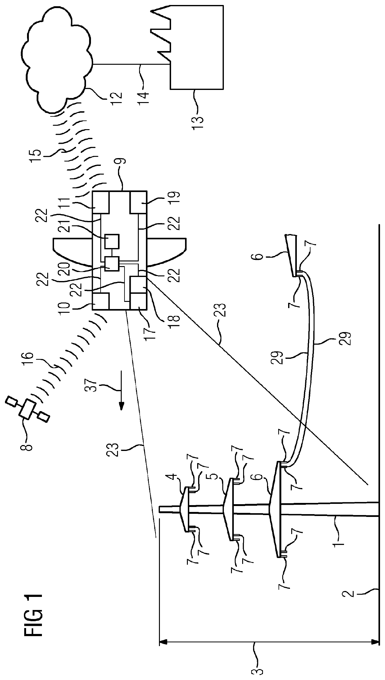
[0059]FIG. 1 shows an exemplary embodiment of an arrangement according to the invention for monitoring a condition of an installation with operating means 7. In this example, the installation is high-voltage masts 1 with high-voltage overhead power lines 29 which are braced between the masts 1. The masts 1 stand freely on the ground 2. In this case, the masts 1 have a typical height 3. A mast 1 is schematically illustrated in the left-hand part of FIG. 1. It has three transverse members 4, 5, 6 at different heights, from each of which two insulators 7 are suspended. The high-voltage overhead power lines 29 are fastened to the insulators 7. For reasons of clarity, only two overhead power lines 29 are illustrated.

[0060]A flying object 9 is used to obtain detailed images of the insulators 7. Damage to the insulators 7 can be detected manually or by machine on the basis of detailed images, with the result that maintenance or replacement of a damaged insulator 7 can be carried out in goo...


PUM


Abstract

A method for condition monitoring of an installation with operating devices, in which overview data is detected by a first vehicle with an overview sensor arrangement for optical detection of the facility, and the operating devices are identified in the overview data by an evaluation device and the positions of the operating devices are determined taking into account the position of the first vehicle. Detail shots of the operating devices are produced by a detail camera on-board a second or the first vehicle, which is oriented in relation to the respective positions of the operating devices. There is a corresponding arrangement for carrying out the method. A mode of embodiment relates to the condition monitoring of high-voltage masts with high-voltage free lines that are clamped between the masts. Insulators hang on the transverse members as operating devices.

Description

CROSS REFERENCE TO RELATED APPLICATIONS[0001]This application is the US National Stage of International Application No. PCT / EP2018 / 056146 filed 13 Mar. 2018, and claims the benefit thereof. The International Application claims the benefit of European Application No. EP17161027 filed 15 Mar. 2017. All of the applications are incorporated by reference herein in their entirety.FIELD OF INVENTION[0002]The invention relates to a method and apparatus for monitoring a condition of an installation.BACKGROUND OF INVENTION[0003]Infrastructures, for instance high-voltage lines, wind turbines or bridge structures, usually have large dimensions. High-voltage masts having mast heights around 100 m are not unusual. A visual inspection by trained personnel, partially with the use of an optical magnification aid, for example binoculars, does not satisfy the requirement of continuous and verifiable documentation and can generally be performed only here and there with a reasonable amount of effort. Fu...

Claims


Application Information

Patent Timeline
Patent Type & Authority Applications(United States)
IPC IPC(8): G06K9/00B64C39/02G05D1/10
CPCB64C2201/127B64C39/024G06K9/00637G05D1/101G01N21/95H02G1/02G01N2021/8867G06T7/0004G06T2207/30108G06T2207/30184G06V20/176G06V20/17B64U2101/30
Inventor BIRCHBAUER, JOSEF ALOISGLIRA, PHILIPPKÄHLER, OLAFKOPPENHÖFER, BERND
Owner SIEMENS ENERGY GLOBAL GMBH & CO KG
Why Eureka
Try Eureka