Improvements relating to reactive power support in wind power plants

a technology of wind power plants and reactive power, which is applied in the direction of wind energy generation, mechanical equipment, machines/engines, etc., can solve the problems of limited reactive power capability of wind turbine generators and particularly expensive solutions, and achieve the effects of avoiding over-thermal capacity of one or more components, and improving system overview

Active Publication Date: 2020-03-05
VESTAS WIND SYST AS
View PDF0 Cites 13 Cited by
  • Summary
  • Abstract
  • Description
  • Claims
  • Application Information

AI Technical Summary

Benefits of technology

[0012]The generator controllers may be configured to alter the model in dependence upon operational conditions of the wind turbine. Operational conditions may comprise current wind speed, ambient temperature, current temperature of components or previously modelled or recorded data. As different generators will face different conditions based upon their placement and continued operation, a single wind power plant thermal model is inadequate, and in allowing turbine-specific models to be created, a much better overview of the system can be maintained, and a safer operation achieved.
[0013]In some embodiments of the invention, the corresponding time limit is determined to avoid exceeding the thermal capacity of the one or more components. A time limit is important to avoid components overheating and being irreparably damaged.

Problems solved by technology

Voltage control capabilities are a requirement of many grid codes, and therefore the limited control capabilities may act as a challenge to grid integration of wind power plants.
However, wind turbines generators have limited reactive power capability, which causes problems when attempting to meet these grid integration requirements.
However, this is a particularly expensive solution.

Method used


Image

  • Improvements relating to reactive power support in wind power plants
  • Improvements relating to reactive power support in wind power plants
  • Improvements relating to reactive power support in wind power plants

Examples


Embodiment Construction

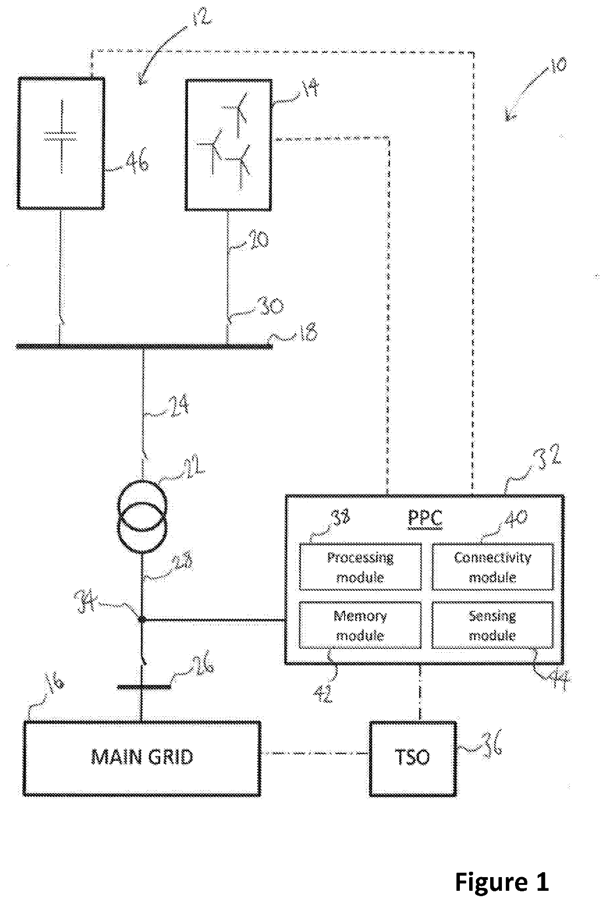
[0033]FIG. 1 illustrates a typical architecture in which a wind power plant (WPP) is connected to a main transmission grid as part of a wider power network. The example shown is representative only and the skilled reader will appreciate other specific architectures are possible, in relation to both wind power plants and power plants for other renewable energy sources. In addition, the skilled reader will appreciate that methods, systems and techniques also described below may be applicable to many different configurations of power network. Moreover, the components of the wind power plant and power network are conventional and as such would be familiar to the skilled reader.

[0034]FIG. 1 shows a power network 10 incorporating a wind power plant (WPP) 12 including a plurality of wind turbine generators (WTGs) 14 often more commonly called ‘wind turbines’. A single WTG would also be possible. Each of the plurality of WTGs 14 converts wind energy into electrical energy, which is transfer...


PUM


Abstract

A wind power plant system comprising: a plurality of wind turbine generators each having a corresponding generator controller, and a power plant controller for controlling the power generated by the wind power plant system; wherein at least some of the plurality of generator controllers are each configured to: generate a model that indicates the thermal capacity of one or more components of the wind turbine generator, determine power capacity data from the model, said data relating to: at least one reactive power supply level and a corresponding time limit for which that reactive power supply level may be maintained, and transmit to the power plant controller the determined power capacity data, wherein the power plant controller is operable to receive the power capacity data from the plurality of generator controllers and to transmit respective power references to the plurality of generator controllers to control the power generated by the wind power plant system.

Description

TECHNICAL FIELD[0001]The present invention relates to a wind power plant system and to a method of controlling a wind power plant. Further aspects of the invention relate to a generator controller for use in a wind power plant system and to a power plant controller for use in a wind power plant system and in a method as described herein.BACKGROUND[0002]It is now expected that newly commissioned wind power plants and other forms of renewable energy are able to offer voltage control at a point of interconnection. A wind power plant comprises a plurality of wind turbine generators and is also known as a wind park or a wind farm. The regulation and general operation of the power plant is controlled by a power plant control system or controller (PPC), which implements operational limits and requirements as set out by a Transmission System Operator (TSO) or in country-specific grid interconnection requirements or ‘grid codes’. The TSO also communicates power delivery demands to the PPC, i...

Claims


Application Information

Patent Timeline
Patent Type & Authority Applications(United States)
IPC IPC(8): H02J3/18H02J3/38F03D9/25
CPCH02J3/1842H02J2203/20F03D9/255H02J3/386H02J3/1885H02J2300/28H02J3/381Y02E10/76Y02E10/72Y02E40/30Y02E60/00Y04S40/20H02J3/50H02J3/38
Inventor BIRIS, CIPRIANGUPTA, MANOJMØLLER, HENRIKNAYEBI, KOUROUSHSIVASANKARAN, JANAKIRAMANWEI, MUBJØRN, HANS KRISTIAN
Owner VESTAS WIND SYST AS
Why Eureka
Try Eureka