
Implementing service function chains

a service function and function chain technology, applied in the field of service function chains, can solve the problems of confusion of users or customers, limited visibility of virtualised items, etc., and achieve the effects of reducing the amount of disruption experienced by users or customers, and reducing the disruption of network upgrades

Active Publication Date: 2020-03-05
BRITISH TELECOMM PLC
View PDF3 Cites 4 Cited by
  • Summary
  • Abstract
  • Description
  • Claims
  • Application Information

AI Technical Summary

Benefits of technology

This patent aims to improve the installation and configuration of new virtual network functions in a way that minimizes network disruption and allows for quick and easy addition and removal of new functions. This is important for service providers as it allows them to offer new options to customers without causing disruption, and also makes network upgrades safer by making it easy to roll back a solution if a problem is detected. Overall, this technology helps to provide more flexibility and efficiency in the delivery of virtual services.

Problems solved by technology

The commonality is that the host software and other virtualised items have limited visibility of the virtualised item, and that the virtualised items have limited visibility of the host.
This means that ARP confusion may occur if two devices holding the same IP address were both to communicate with the same node.
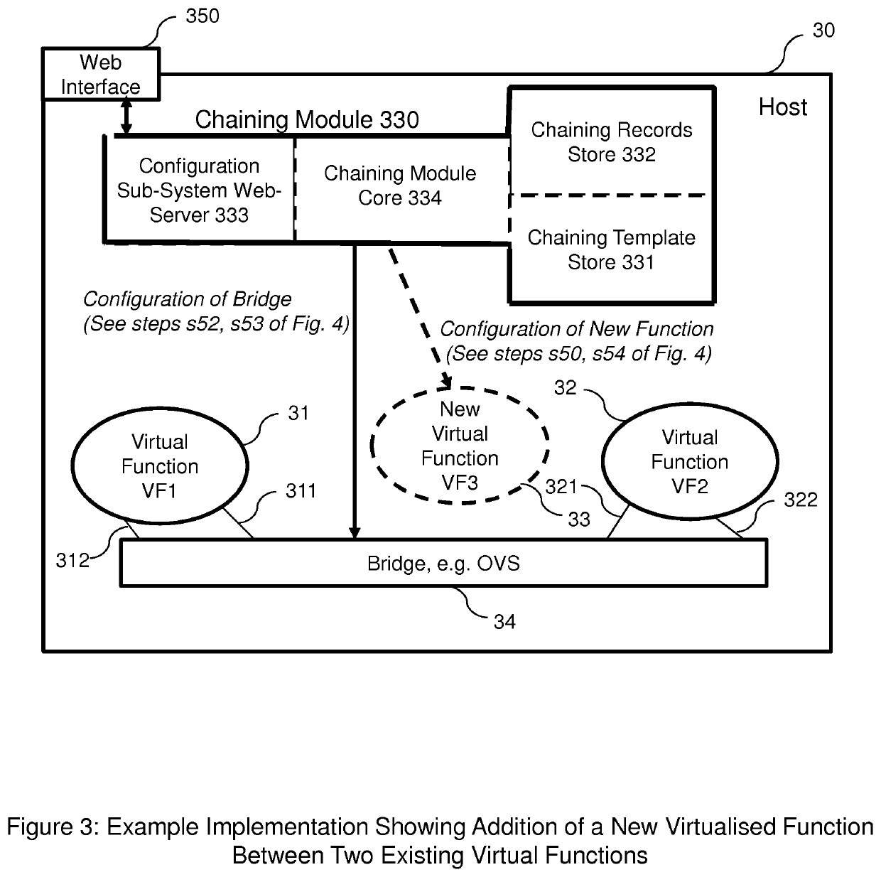
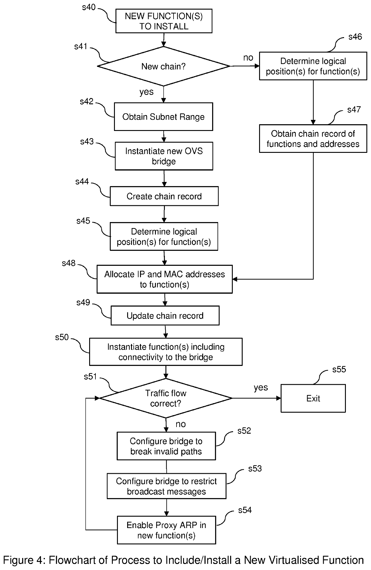
In relation to the implementation of virtualised service function chains, it would be useful to be able to rely on Proxy ARP, but with virtualised functions, the mere use of Proxy ARP would be insufficient on its own for reasons such as the following:If a bridge is used to connect the service functions, several functions on the virtual network could simultaneously reply to ARP broadcast messages, leading to erratic behaviour, and significant traffic bypassing any new virtual function added to the service function chain after its initial creation and configuration.If virtual Ethernet software constructs were used to connect the virtualised service functions, these cannot be moved between functions, so new virtual Ethernet pairs would be needed between the new and old functions and all these Ethernet constructs would need to be configured on the original functions as well as on the new functions.

Method used


Image

  • Implementing service function chains
  • Implementing service function chains
  • Implementing service function chains

Examples


Embodiment Construction

[0062]With reference to the accompanying figures, methods and apparatus according to a preferred embodiment will be described.

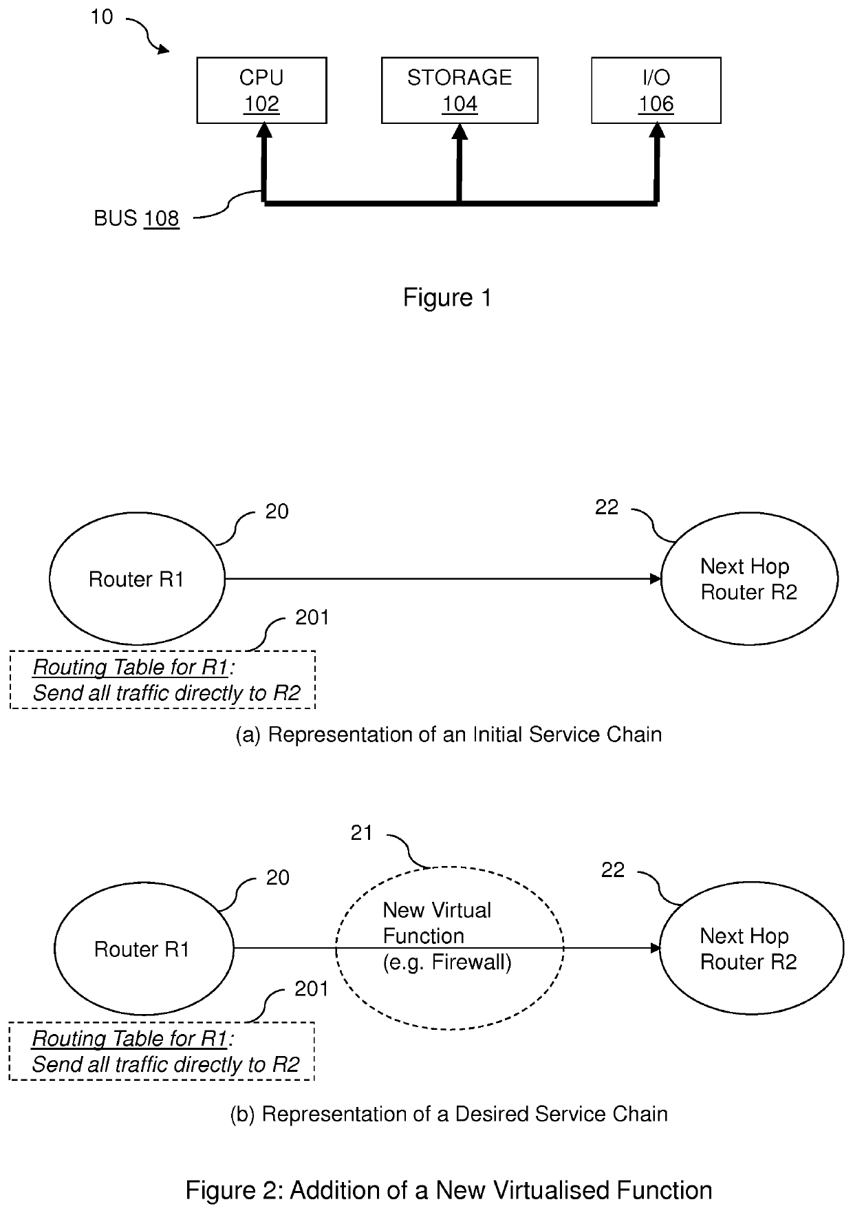
[0063]FIG. 1 is a block diagram of a computer system 10 suitable for operating embodiments of the invention. A central processor unit (CPU) 102 is communicatively connected to a data store 104 and an input / output (I / O) interface 106 via a data bus 108. The data store 104 can be any read / write storage device or combination of devices such as a random access memory (RAM) or a non-volatile storage device, and can be used for storing executable and / or non-executable data. Examples of non-volatile storage devices include disk or tape storage devices. The I / O interface 106 is an interface to devices for the input or output of data, or for both input and output of data. Examples of I / O devices connectable to I / O interface 106 include a keyboard, a mouse, a display (such as a monitor) and a network connection.

[0064]A method according to a preferred embodiment will be...


PUM


Abstract

Methods and apparatus are disclosed for configuring one or more processors to implement service function chains comprising one or more virtualised service functions. A method according to one aspect, performed by a processing module (330) implemented on one or more processors (30), involves steps being performed in respect of at least one new virtualised service function (33) to be included in a service function chain of: determining a position in the service function chain at which the new virtualised service function (33) is to be included; allocating at least one internal address to the new virtualised service function, the at least one internal address being an address to be usable by a switching processor (34); and providing to the switching processor (34) an indication of the at least one internal address allocated to the new virtualised service function (33).

Description

TECHNICAL FIELD[0001]The present invention relates to methods and apparatus for implementing service function chains comprising one or more virtualised service functions on one or more computer processors, and in particular to methods and apparatus for including new virtualised service functions in service function chains.BACKGROUND TO THE INVENTION AND PRIOR ART[0002]Traditionally, different network functions were generally provided as individual pieces of equipment (hardware) each with their own individual interfaces. Software installed on the hardware controls the hardware including all of its network interfaces. Examples of such network functions are firewalls, routers and performance monitoring equipment. These functions are typically provided in a chain that data traffic traverses before reaching its end destination. Today, such functions can be provided as software functions that can co-exist on commodity hardware. This can reduce costs, and can also speed up service provisio...

Claims


Application Information

Patent Timeline
Patent Type & Authority Applications(United States)
IPC IPC(8): H04L12/24H04L29/12H04L12/741H04L45/74
CPCH04L61/20H04L45/74H04L41/0806H04L61/6095H04L67/10H04L41/0813H04L61/103H04L61/35H04L61/5007H04L41/0897H04L61/50H04L2101/695
Inventor KRUG, ANNE-LOUISE
Owner BRITISH TELECOMM PLC
Learn More