Machine tool

a technology for machine tools and tools, applied in the direction of metal-working machine components, metal-working apparatus, maintainance and safety accessories, etc., can solve the problems of requiring a lot of labor, deterioration of machines, and shortening of tool life, so as to suppress the scattering of chips and the effect of discharging chips

Active Publication Date: 2020-03-12
FANUC LTD
View PDF0 Cites 3 Cited by
  • Summary
  • Abstract
  • Description
  • Claims
  • Application Information

AI Technical Summary

Benefits of technology

[0024]As a result, the machine tool according to the present invention is capable of preferably discharging the chips while suppressing scattering of the chips, even in the case of machining such as cutting or grinding of a machining object such as of graphite, resin or CFRP whose generated fine chips are hardly suppressed from scattering in the dry machining region by a conventional method.

Problems solved by technology

These materials such as of CFRP, resin and graphite have problems in machining such as generation of crack and deformation, and are thus subjected to so-called dry machining, in which dry cutting, dry grinding or the like is carried out without coolant.
However, since graphite is a powder sintered compact mainly composed of fine carbon particles, powdered chips are generated during machining such of cutting and grinding, and enter the sliding portion or the machine tool, thereby causing problems, for example, progress in deterioration of a machine due to occurrence of abrasion on the sliding surface, or extremely shortening of a tool life.
Even in the case where material which produces fine chips, for example, resin and CFRP, is subjected to machining, there are various problems in that disposing of the fine chips requires a lot of labor, the chips scatter and cause a mechanical problem, and the chips may cause health problems.

Method used


Image

  • Machine tool

Examples


Embodiment Construction

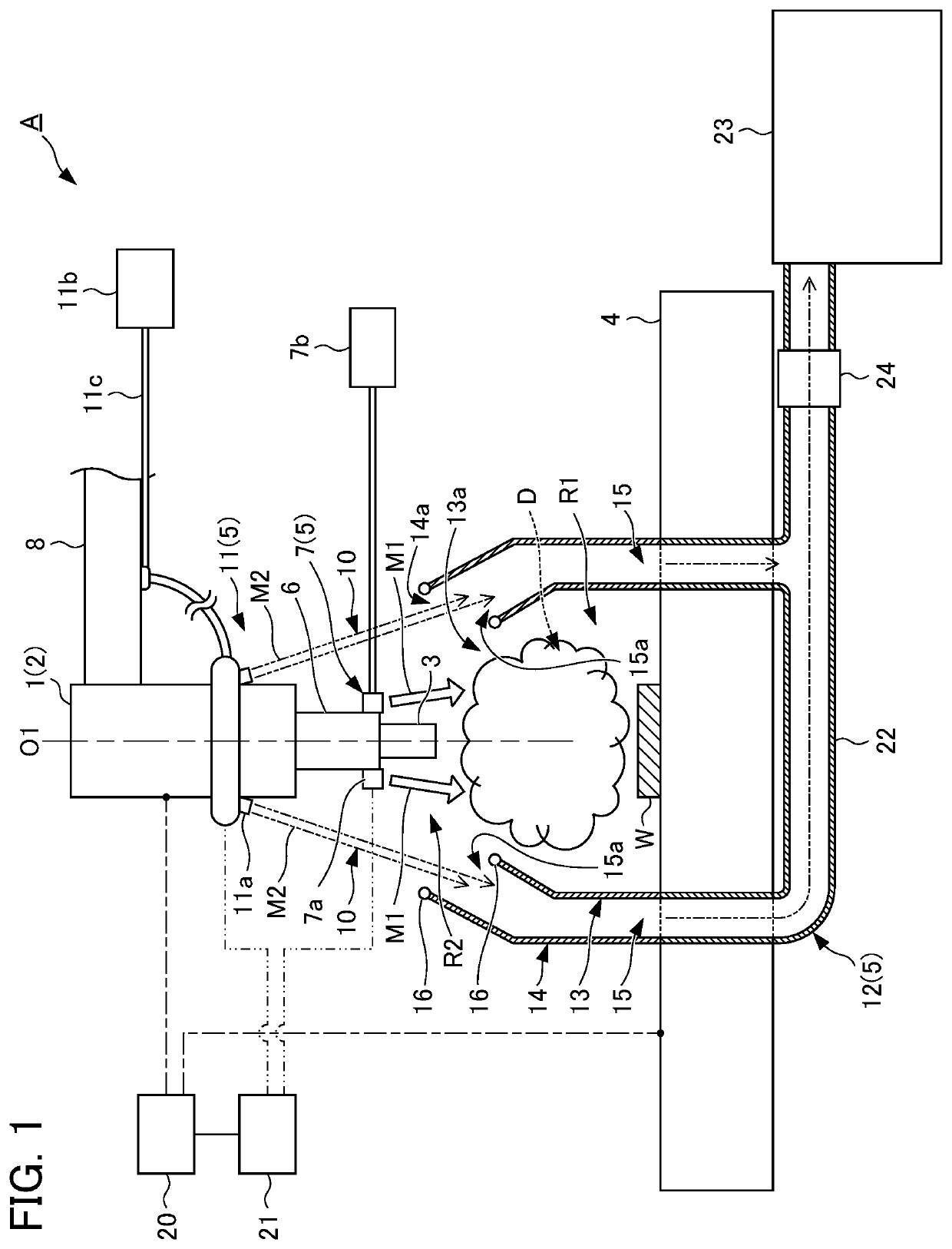
[0026]A machine tool according to one embodiment of the present invention will be described below with reference to FIG. 1.

[0027]The machine tool according to the present embodiment is, for example, a machining center for performing removing (cutting, grinding, etc.) to a machining object made of metal, graphite, resin, CFRP or the like to form a predetermined shape. It is noted that the machine tool according to the present invention is applicable to not only a machine tool including a machining center, but also various cases in which a workpiece is subjected to cutting, grinding or the like with a tool.

[0028]Specifically, as shown in FIG. 1, a machine tool A according to the present embodiment is configured with, for example, a machine tool main body 2, a spindle 1 arranged with an axis line O1 thereof directed along the up-down direction, rotationally-driving means (not shown) for rotationally driving the spindle 1 around the axis line O1, a tool 3 attached to the spindle 1, a ta...


PUM


Abstract

A chip antiscatter mechanism is included and configured to suppress scattering of chips generated during machining of a machining object. The chip antiscatter mechanism includes chip stirring means configured to stir the chips, by jetting a gas into a dry machining region above a table including the machining object, fluid curtain forming means configured to form a fluid curtain by jetting a fluid such as liquid or gas membranously from above to an outside of the dry machining region so as to surround the dry machining region, and to form a closed region including the dry machining region by the membranous fluid curtain, and discharging means configured to receive and discharge the fluid jetted membranously by the fluid curtain forming means.

Description

[0001]This application is based on and claims the benefit of priority from Japanese Patent Application No. 2018-168155, filed on 7 Sep. 2018, the content of which is incorporated herein by reference.BACKGROUND OF THE INVENTIONField of the Invention[0002]The present invention relates to a machine tool, particularly to a machine tool capable of preferably suppressing scattering of the chips generated during machining.Related Art[0003]In an example, conventionally in the case of cutting or grinding a workpiece serving as a machining object by a machine tool, the chips thereof enter the sliding surface or the like of the machine tool, thereby causing problems such as abrasion and shortening of the tool life. The scattering of the chips is thus suppressed. It is noted that, in the present specification, the term “chips” is broadly interpreted and includes powdery “chips.”[0004]Examples of the measure to suppress scattering of the chips include the method of supplying liquid to a machinin...

Claims


Application Information

Patent Timeline
Patent Type & Authority Applications(United States)
IPC IPC(8): B23Q11/00B23Q11/08
CPCB23Q11/0046B23Q11/0883B23P23/04B23Q11/10B23Q11/0858B23Q11/006
Inventor TANGO, CHIKARA
Owner FANUC LTD
Why Eureka
Try Eureka