Method for producing a vibration-damping structure combination for damping vibrations of movable masse

a technology of vibration-damping structure and movable mass, which is applied in the direction of shock absorbers, machines/engines, turbines, etc., can solve the problems of vibration the operating parameters of the rotor blade may also change, and the vibration of the guide vanes

Pending Publication Date: 2020-03-12
SIEMENS ENERGY GLOBAL GMBH & CO KG
View PDF13 Cites 3 Cited by
  • Summary
  • Abstract
  • Description
  • Claims
  • Application Information

AI Technical Summary

Benefits of technology

[0030]Preferably, at least one region of the first structure is formed enclosed by the further structure, and/or at least one region of the further structure is formed enclosed by the first structure, so that the further structure is undetachable from the first structure. By virtue of the fact that at least one region of the further structure is formed enclosed by the first structure and/or at least one region of the first structure is formed enclosed by the further structure, the two structures are connected inseparably to one another and can move relative to one another in all directions and/or in all direction c...

Problems solved by technology

The positive or negative rotational accelerations of the rotor blades may cause vibrations of the rotor blades.
Because operating parameters of the rotor blades may also change because of changes in the operation of the turbine, vibrations may also occur in the guide vanes.
The cracks may lead during operation of the turbine...

Method used


Image

  • Method for producing a vibration-damping structure combination for damping vibrations of movable masse
  • Method for producing a vibration-damping structure combination for damping vibrations of movable masse
  • Method for producing a vibration-damping structure combination for damping vibrations of movable masse

Examples


Embodiment Construction

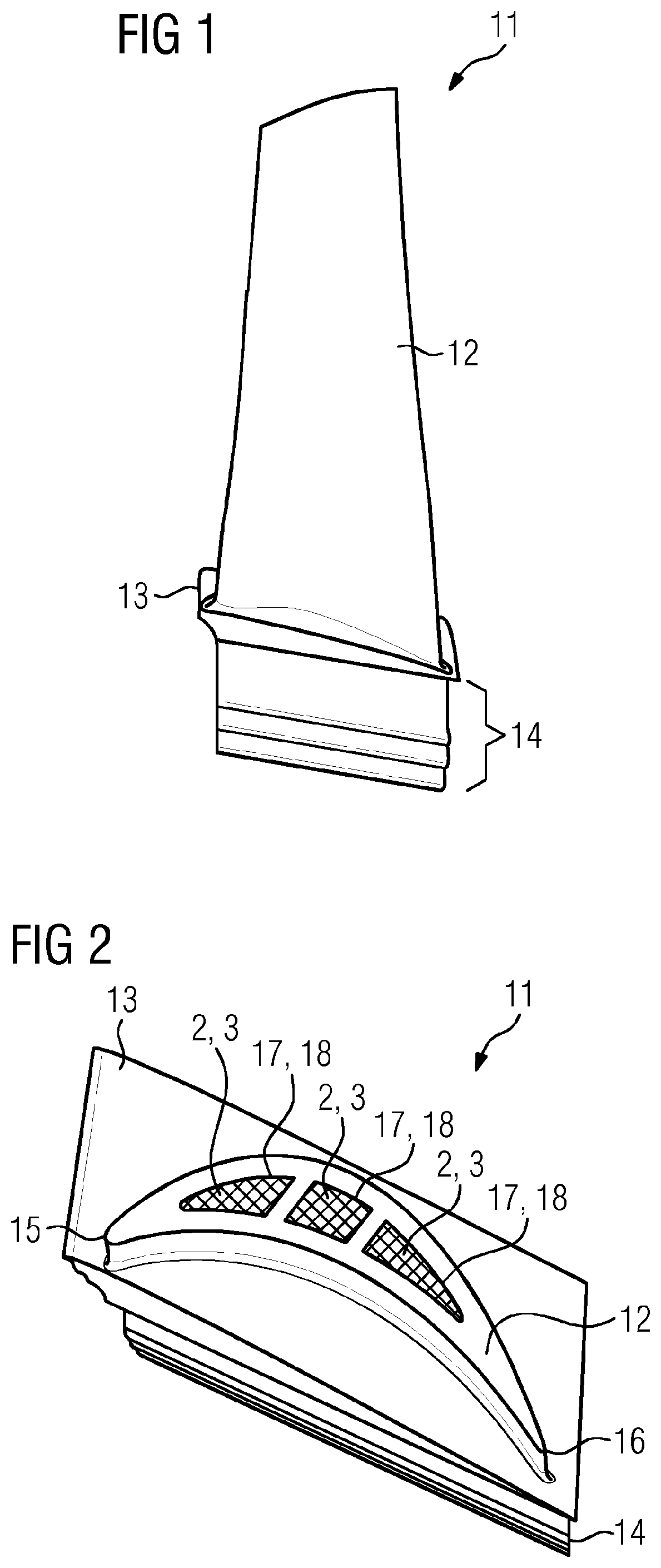
[0043]Reference is first made to FIGS. 1 and 2.

[0044]FIGS. 1 and 2 show a turbine blade 11 of a rotating turbomachine.

[0045]The rotating turbomachine may be a turbine or a compressor, respectively having a rotor with a plurality of rotor blades and a stator with a plurality of guide vanes. The turbine blade 11 shown in FIGS. 1 and 2 is in the present exemplary embodiment configured as a rotor blade. In contrast to the present exemplary embodiment, the turbine blade 11 may also be configured as a guide vane.

[0046]In the present exemplary embodiment, the turbine blade 11 comprises a blade body 12, a platform 13 and a fastening section 14.

[0047]By means of the fastening section 14, the turbine blade 11 can be connected to the rotor. The fastening section 14 is bound by the platform 13, which separates the fastening section 14 from the blade body 12. The blade body 12 comprises a blade front edge 15, a blade rear edge 16 and blade cavities 17. The blade body 12 extends starting from the...


PUM

PropertyMeasurementUnit
Structureaaaaaaaaaa

Abstract

A method for producing a vibration-damping structure combination for damping vibrations for movable masses, having a first structure and a further structure, the further structure movable within a stop surface defined by a first structure surface of the first structure. The method includes a) providing the first structure, having the first structure surface and which defines a coating surface of a coating at least in some sections; b) coating the first structure surface of the first structure with the coating, the coating surface of the coating being applied such that a cavity is formed; c) filling the cavity with the filler; d) curing the filler until the further structure having a further structure surface is formed, which lies against the coating surface; and e) removing the coating, the further structure thus being movable relative to the first structure within the stop surface defined by the first structure surface.

Description

CROSS REFERENCE TO RELATED APPLICATIONS[0001]This application is the US National Stage of International Application No. PCT / EP2018 / 063041 filed 18 May 2018, and claims the benefit thereof. The International Application claims the benefit of German Application No. DE 10 2017 208 631.9 filed 22 May 2017. All of the applications are incorporated by reference herein in their entirety.FIELD OF INVENTION[0002]The invention relates to a method for producing a vibration-damping structure combination, to an intermediate product of the method for producing the vibration-damping structure combination, and to a structure combination for damping vibrations of movable masses.BACKGROUND OF INVENTION[0003]A rotating turbomachine, a turbine for example for example for a power plant, comprises a rotor having a plurality of rotor blades and a stator having a plurality of guide vanes. During operation of the turbine, the rotor moves about a rotation axis with a particular rotational speed so that the r...

Claims


Application Information

Patent Timeline
IPC IPC(8): F16F7/10F01D5/18F01D25/06B22D19/00B33Y80/00
CPCF01D5/18F16F7/10B22D19/00F05D2220/30F05D2240/24F01D25/06B33Y80/00F05D2260/96F05D2250/28B22F5/04B23P15/02F01D5/147F01D5/16F01D5/26F01D25/04F05D2250/283F05D2250/282F05D2300/60F16F7/104B22F3/10C22C1/04B22F2998/10B22F2999/00Y02P10/25B22F3/1115B22F7/06B22F5/10B22F10/28B22F7/062B23P15/04
Inventor BLANK, ROBINFARAHBOD-STERNAHL, LENAKIENER, CHRISTOPHKYECK, SASCHA MARTINKÜSTERS, YVESPURSCHKE, SIMONREYMANN, HELGE
Owner SIEMENS ENERGY GLOBAL GMBH & CO KG
Why Eureka
Try Eureka