

Flexible oleo display and method for manufacturing the same
- Summary
- Abstract
- Description
- Claims
- Application Information
AI Technical Summary
Benefits of technology
Problems solved by technology
Method used
Image

Examples
Embodiment Construction
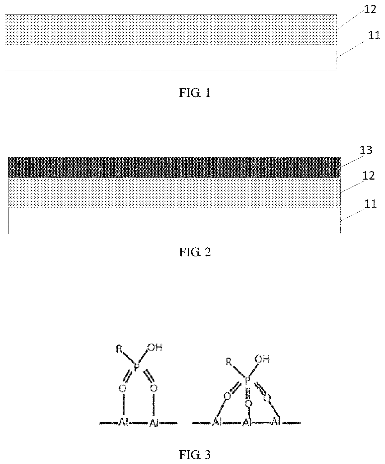
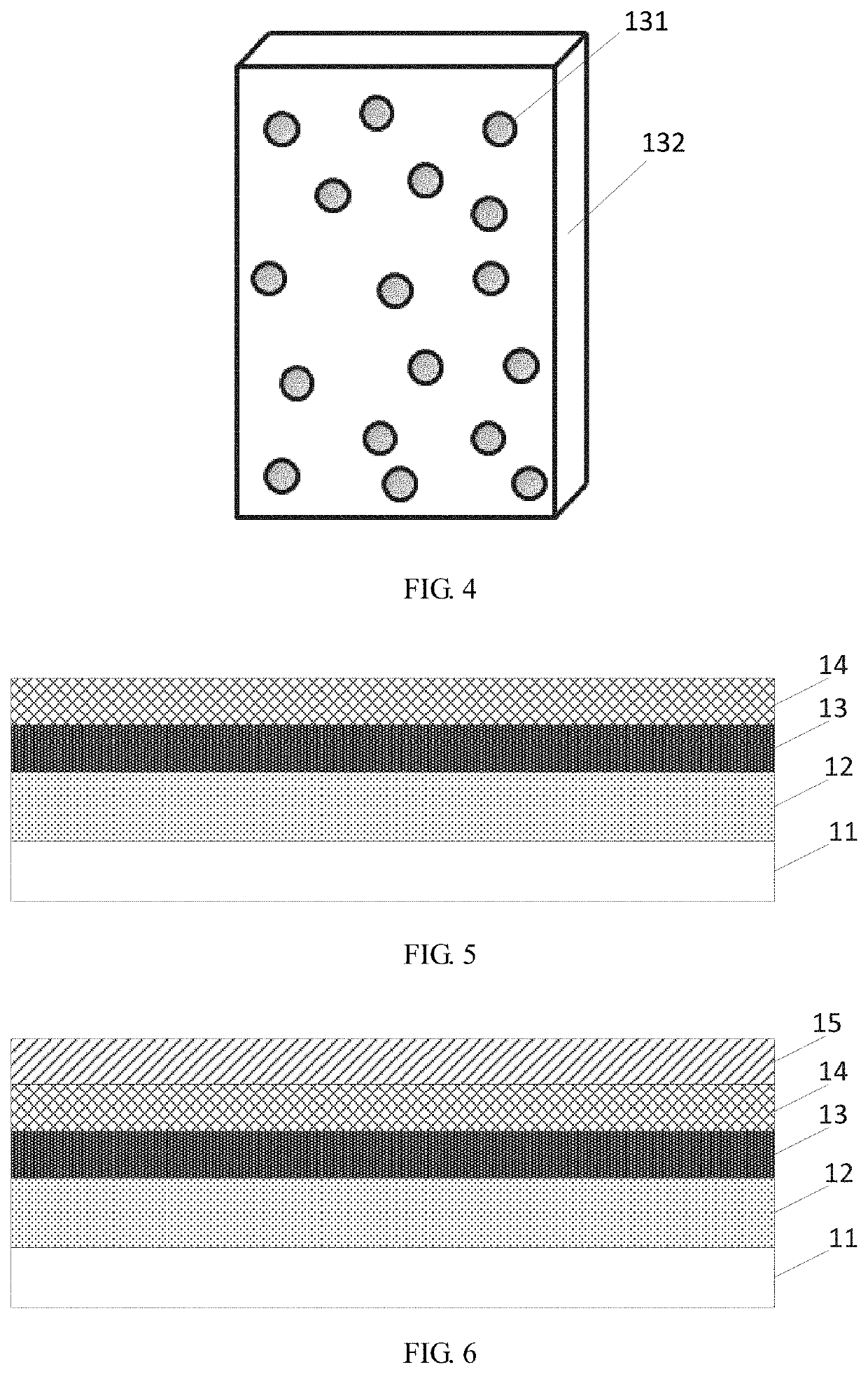
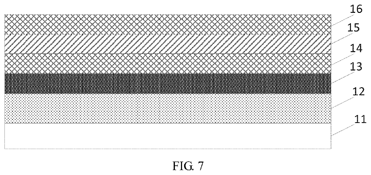
[0050]The following embodiments refer to the accompanying drawings for exemplifying specific implementable embodiments of the present disclosure. Moreover, directional terms described by the present disclosure, such as upper, lower, front, back, left, right, inner, outer, side, etc., are only directions by referring to the accompanying drawings, and thus the used directional terms are used to describe and understand the present disclosure, but the present disclosure is not limited thereto. In the drawings, the same reference symbol represents the same or similar components.
[0051]Please refer to FIG. 1. FIG. 1 is a schematic diagram showing a first step of a method for manufacturing a flexible OLED display according the present disclosure.
[0052]The method for manufacturing a flexible OLED display according the present disclosure comprises the following steps.
[0053]In step S101, an organic light-emitting display layer is formed on a flexible substrate.
[0054]As shown in FIG. 1, an orga...
PUM
 Abstract
Description
Claims
Application Information