Method for supporting a user, computer program product, data medium and imaging system

a technology for imaging systems and users, applied in the field of supporting users, can solve problems such as inaccuracy or uncertainty in registration, disadvantageous consequences, etc., and achieve the effects of improving or maximizing the positioning accuracy of instruments, less adverse effects on target objects, and greater accuracy or reliability

Active Publication Date: 2020-03-19
SIEMENS HEALTHCARE GMBH
View PDF0 Cites 2 Cited by
  • Summary
  • Abstract
  • Description
  • Claims
  • Application Information

AI Technical Summary

Benefits of technology

[0038]The path may be specified, for example, such that the instrument moves or is able to move along the path as little as possible in the specified spatial direction of greatest uncertainty and / or with minimal deviation between the alignment of the instrument and the specified spatial direction. It is thereby possible overall to improve or maximize a positioning accuracy of the instrument in relation to the target object or the predetermined target, and accordingly, the predetermined target may be reached with greater accuracy or reliability and, if applicable, less adverse effect on the target object. The instrument typically has a limited range of effect, for example. Due to the uncertainty of the 2D / 3D registration, an additional way point or position of effect (e.g., deployment position) of the instrument may then be planned or provided as part of the path (e.g., in the specified spatial direction), such that the predetermined target (e.g., a lesion of the target object) is included in or covered by the range of effect of the instrument despite the registration uncertainty. In this case, the effect of the instrument may be or include, for example, depiction of the predetermined target, optionally with a predetermined minimal image sharpness, or also manipulation of the target object or the predetermined target (e.g., collection of a sample and / or an ablation).
[0039]In a development, a preferred direction of an effect of the instrument is taken into consideration for the purpose of specifying the path. In other words, a spatial anisotropy of the effect or range of effect of the instrument is therefore taken into consideration. For example, the instrument may be a biopsy needle for the purpose of sample collection, by which a plurality of samples may be collected along the path (e.g., in a movement direction of the biopsy needle but not in sideways directions relative thereto).
[0040]In order to provide that a sample is actually collected from the respectively predetermined target or target region, it is advantageous, for example, for the path to be planned or specified such that the instrument, while being guided along the specified path in the region of the predetermined target according to the application case (e.g., according to the shape of the predetermined target region), moves along or, for example, perpendicular to the specified spatial direction of greatest uncertainty of the 2D / 3D registration. Taking the preferred direction of the instrument or the effect of the instrument into consideration, it is likewise possible by virtue of planning or specifying the path in a corresponding manner, for example, to achieve a maximum overlap between the range of effect of the instrument and the predetermined target, taking the registration inaccuracy and visualization inaccuracy or uncertainty into consideration. For example, an ablation zone in the case of a needle ablation may not be circular or spherical but elliptically elongated along an axis of an ablation needle that is used correspondingly. If, for example, tumor tissue is to be removed, the present embodiments make it possible to provide with greater probability or reliability that the tumor tissue is actually situated completely within a volume or range of effect of the ablation (e.g., within the ablation zone), and that surrounding tissue is not affected or is affected as little as possible in this case.
[0041]It is therefore possible, using the present embodiments, to specify an improved path for an interventional or surgical instrument having an effect on a target object (e.g., body tissue) that has a geometric preferred direction or spatial anisotropy. This is achieved by taking into consideration the preferred direction or anisotropy and the spatially anisotropic uncertainty or inaccuracy of the 2D / 3D registration and hence of the overlay image likewise.
[0042]In a further embodiment, the instrument itself is represented in the overlay image (e.g., as an image or a model). As the signal, as part of the signal, or using the signal, the representation of the instrument and / or a range of influence or range of effect of the instrument in the overlay image is then broadened in a spatially anisotropic manner as a function of the respective local uncertainty of the 2D / 3D registration. In other words, the representation of the instrument and / or a range of effect of the instrument may therefore be distorted in accordance with the uncertainty of the 2D / 3D registration and thus in accordance with an uncertainty of the visualization or representation of the overlay image. Since the relevant user is typically familiar with the instrument, the type, degree, and direction of the uncertainty or of a corresponding visualization error may thus be displayed to the user in a manner that is particularly simple, intuitively understandable, and not unnecessarily distracting. If the instrument actually has, for example, a cylindrical or rod-shaped form or shape, this may be broadened (e.g., elliptically) in the overlay image according to the current alignment of the instrument in relation to the specified spatial direction. The representation of the range of effect may be adapted correspondingly.
[0043]The anisotropic broadening of the representation may equally signify that the representation of the instrument in the overlay image is surrounded by a corresponding broadening zone or uncertainty zone (e.g., a correspondingly marked spatial region). For example, a path for the instrument may then be planned or traced automatically or by the respective user. The path guides the instrument such that the entire broadened representation of the instrument or a range of effect of the instrument passes through the predetermined target (e.g., a lesion or similar) and therefore, acquires the target completely. It is thus possible to provide that despite the registration uncertainty, all possible instrument paths within a region indicated or displayed by the broadened representation actually pass through or encounter the predetermined target (e.g., the lesion or a tumor or similar). For example, if the range of effect of the instrument is smaller than the broadened representation, it is possible to plan or trace, for example, a plurality of positions of effect or deployment positions accordingly (e.g., a plurality of sample collection points or a plurality of adjacent paths through the predetermined target or in the region of the predetermined target), such that an overlap of the predetermined target with the entire broadened representation and / or with the range of effect of the instrument is provided.

Problems solved by technology

Errors, inaccuracies, or uncertainties in the registration may have disadvantageous consequences, accordingly.

Method used


Image

  • Method for supporting a user, computer program product, data medium and imaging system

Examples


Embodiment Construction

[0058]The exemplary embodiments explained below are variants of the invention. In the exemplary embodiments, the components of the embodiment variants, as described, represent in each case individual features of the invention, being regarded as independent of each other. The features respectively develop the invention independently of each other likewise and are therefore also to be considered as constituents of the invention individually or in a combination other than that shown or described. The embodiment variants as described may also be supplemented by further features of the invention described above.

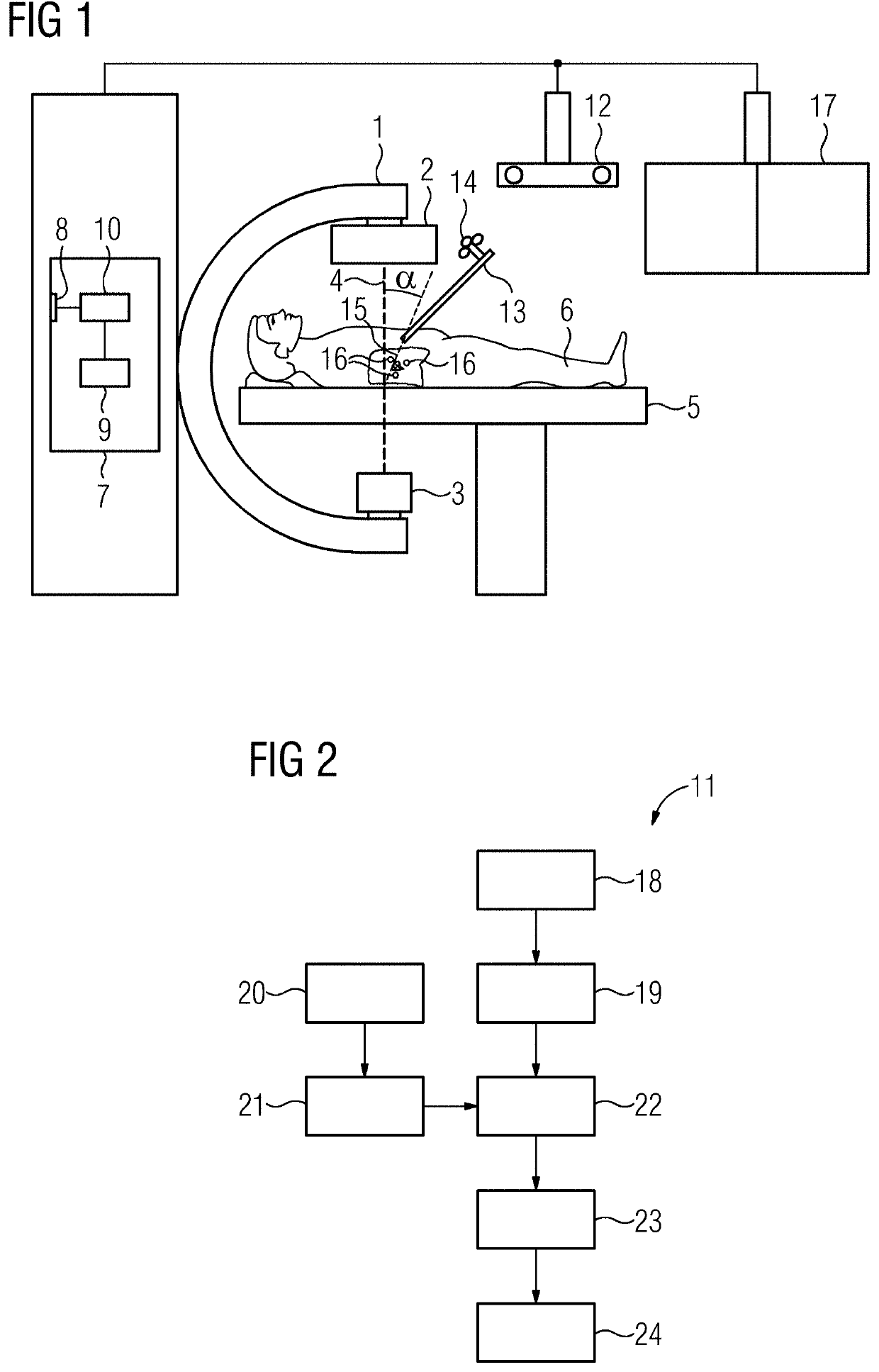
[0059]FIG. 1 shows a schematic representation of one embodiment of an imaging system 1 configured as, for example, a C-arm X-ray device. The imaging system 1 in this case has a radiation source 3 and a detector 2 for detecting X-radiation emitted by the radiation source 3. Using the X-radiation (e.g., by the imaging system 1), a target object may be depicted along or in a recordin...


PUM


Abstract

A method for supporting a user, a corresponding computer program product, a corresponding data medium, and a corresponding imaging system are provided. According to the method, a three-dimensional (3D) data set depicting a target object is provided, and at least one two-dimensional (2D) image of the target object is automatically acquired. The 2D image and the 3D data set are automatically registered with each other by a 2D/3D registration. A spatial direction in which the 2D/3D registration exhibits greatest uncertainty is automatically specified. A signal for aligning an instrument that is provided for the purpose of examining the target object is then automatically generated and output as a function of the specified spatial direction in order to support the user.

Description

[0001]This application claims the benefit of EP 18195330.8, filed on Sep. 19, 2018, which is hereby incorporated by reference in its entirety.BACKGROUND[0002]The present embodiments relate to supporting a user.[0003]There nowadays exists a multiplicity of different imaging modalities, these being employed in a medical environment, for example, but likewise also in other industrial fields for the purpose of depicting a respective target object or examination object. A technique that is nowadays widely used in this case combines data from different sources, where the corresponding data (e.g., images or data sets) are registered with each other so that the images or data sets may be overlaid in a positionally accurate manner within a shared coordinate system. In order that a respective situation may be recognized and evaluated as accurately and reliably as possible, or in order that the depicted examination object may be, for example, manipulated as accurately and reliably as possible,...

Claims


Application Information

Patent Timeline
Patent Type & Authority Applications(United States)
IPC IPC(8): A61B1/00G06T7/20G06T7/30A61B6/12A61B6/00A61B10/04
CPCA61B1/00009A61B6/4441G06T2207/10116G06T2207/30004G06T7/20A61B1/0005A61B1/00193A61B2010/045A61B6/12G06T7/30A61B6/5223A61B10/04A61B6/032A61B6/5235A61B6/5247A61B5/055A61B1/05A61B1/3132A61B10/0233A61B34/20A61B34/10A61B2034/107G06T2207/10068G06T2207/10072A61B6/487A61B2034/301A61B1/000095
Inventor REGENSBURGER, ALOIS
Owner SIEMENS HEALTHCARE GMBH
Why Eureka
Try Eureka