Combined continuous casting and metal strip hot-rolling plant

a continuous casting and hot-rolling technology, applied in metal rolling, manufacturing tools, work heating devices, etc., can solve the problems of low-carbon steels, limited hot-rolling, and inability to completely replace cold-rolled products with hot-rolled products

Active Publication Date: 2020-03-19
DANIELI & C OFF MEC SPA
View PDF0 Cites 2 Cited by
  • Summary
  • Abstract
  • Description
  • Claims
  • Application Information

AI Technical Summary

Benefits of technology

[0016]It is the primary object of the present invention to provide a combined continuous casting and metal strip hot-rolling plant which makes it possible to roll a wider range of products, and to obtain output thicknesses even thinner than 0.8 mm, whereby avoiding the difficulties of handling thin strips with respect to the solutions of the prior art.
[0017]It is another object of the invention to provide a plant which allows the continuous hot-rolling also of products which according to the prior art must be cold-rolled to obtain good mechanical properties, whereby dramatically reducing the processing cost and the crossing time through the entire plant for new products which, after hot-rolling, can replace those made using cold-rolling cycles, because the same properties are obtained from the process.

Problems solved by technology

Despite the development of the art, limitations which prevent completely replacing cold-rolled products with hot-rolled products, in the case of low-carbon steels, still remain.
This means that, in order to obtain high quality products, low-carbon steel slabs must be cold-rolled, and therefore it is not possible hot-rolling only, immediately after the continuous casting.
So, disadvantageously two dedicated rolling lines are needed, one for hot rolling and another one for cold rolling, and the product processing completion time is very long.
Disadvantageously, from a dimensional point of view, the possibility of cutting and winding strips thinner than 0.6-0.8 mm is also extremely complex because of the high risk of jamming while handling the head and leading it in, with the consequent blocking of the entire casting and rolling process.
In addition, when rolling in austenitic range, there is a limit related to the mechanical properties of the product.
This limits the use of hot-rolled strips to bending uses only, and in general to uses with very low deformations during moulding.
Consequently, the possibility of replacing cold-rolled products with hot-rolled products is limited by the abovesaid problems.
Finally, the current range of Advanced High Strength Steels (AHSS) which can be obtained by known plants is limited, whereby reducing the production mix of types of steel which can be obtained with these plants.

Method used


Image

  • Combined continuous casting and metal strip hot-rolling plant
  • Combined continuous casting and metal strip hot-rolling plant
  • Combined continuous casting and metal strip hot-rolling plant

Examples


Embodiment Construction

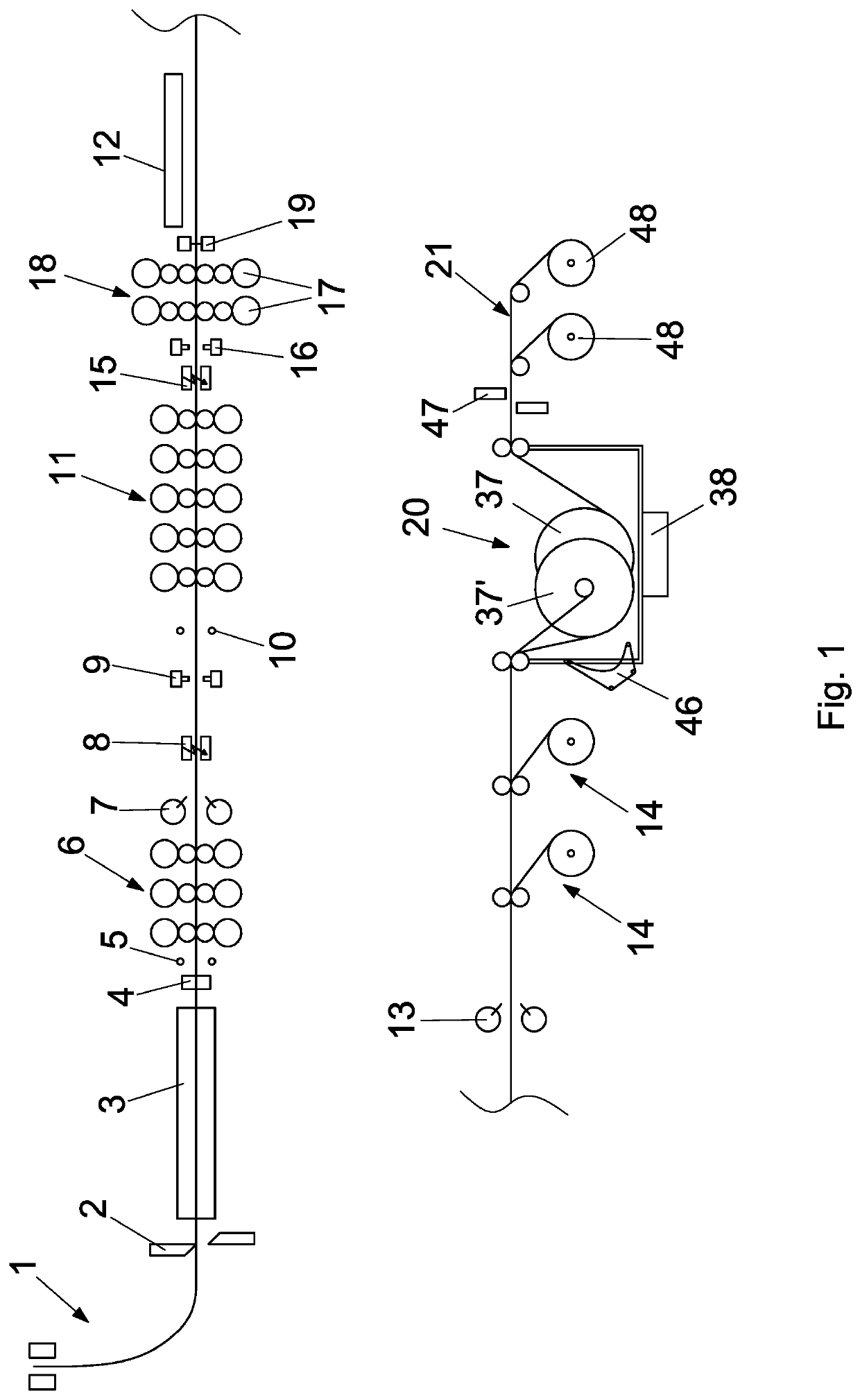
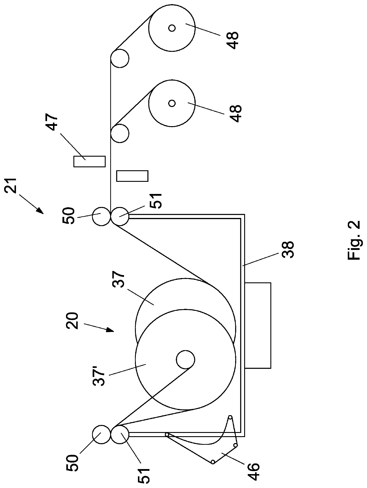
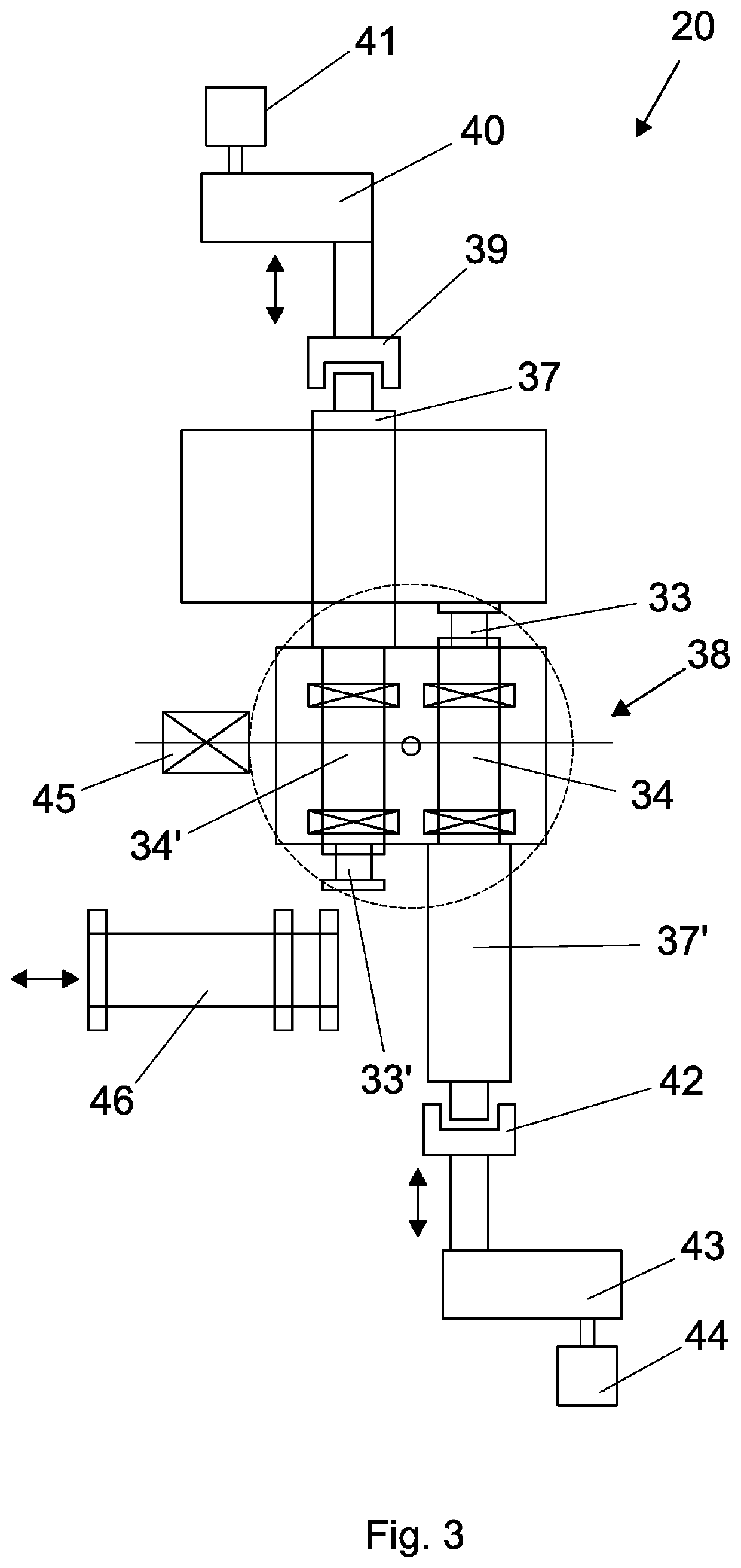
[0064]Figures from 1 to 6 show preferred embodiments of a combined plant of continuous casting and rolling of thin slab to obtain a strip in endless mode to obtain coils of strip. The material of the strip is preferably steel.

[0065]The plant, which is object of the present invention, in all its embodiments, comprises in succession:[0066]a continuous casting machine 1 for casting a slab, preferably a slab having a thickness comprised between 30 and 140 mm;[0067]a first rolling mill 6 or roughing mill, preferably comprising one to four rolling stands, in order to perform a hot roughing of the slab and to obtain a blank, i.e. the so-called transfer bar;[0068]a second rolling mill 11 or finishing mill, preferably comprising from three to seven rolling stands, in order to perform a hot finishing of the transfer bar and to obtain a strip;[0069]a third rolling mill 18, comprising at least two rolling stands 17, for further reducing the thickness of the strip; said at least two rolling stan...


PUM

PropertyMeasurementUnit
diameteraaaaaaaaaa
diameteraaaaaaaaaa
thicknessaaaaaaaaaa

Abstract

A combined continuous casting and endless rolling plant for a metal strip, comprising—a continuous casting line (1) for casting a slab;—a first rolling mill (6) for roughing the slab and for obtaining a transfer bar;—a second rolling mill (11) for finishing the transfer bar and for obtaining a strip;—a third rolling mill (18), comprising at least two rolling stands (17), for further reducing the N thickness of the strip;—accumulation means (20) of the strip comprising at least one first reel (37, 37′) dimensioned to wind and unwind a coil weighing from 80 to 250 metric tons and / or up to 6 meters in diameter, named mega coil;—first cutting means (13), arranged between said third rolling mill (18) and said accumulation means (20), configured to cut the strip after the mega coil has been wound on the at least one first reel (37, 37′);—at least one second reel (48) for winding portions of strip, unwound from said accumulation means (20), up to a predetermined weight limit or coil diameter limit;—second cutting means (47), arranged between said accumulation means (20) and said at least one second reel (48), adapted to cut the strip whenever a portion of strip wound on the at least one second reel (48) reaches said predetermined weight limit or coil diameter limit.

Description

CROSS REFERENCE TO RELATED APPLICATION(S)[0001]The present application claims priority to PCT International Application No. PCT / IB2018 / 0517445 filed on Mar. 15, 2018, which application claims priority to Italian Patent Application Nos. 102017000028732 filed Mar. 15, 2017, the entirety of the disclosures of which are expressly incorporated herein by reference.STATEMENT RE: FEDERALLY SPONSORED RESEARCH / DEVELOPMENT[0002]Not Applicable.FIELD OF THE INVENTION[0003]The present invention relates to a combined continuous casting and metal strip hot-rolling plant in austenitic range or in ferritic range, able to produce rolled strips in the form of coils.PRIOR ART[0004]The development of thin slab continuous casting plant technology has led to a remarkable development of combined plants in which casting is coupled with hot rolling. An example of such plants is described in document EP0980723A2.[0005]In relation to the arrangement of the plant and to the installed auxiliary plants, three type...

Claims


Application Information

Patent Timeline
Patent Type & Authority Applications(United States)
IPC IPC(8): B21B1/46B21B1/26
CPCB21B1/26B21B2015/0057B21B2015/0014B21B1/463B21B2201/04B21B45/004B21B1/24B21B2015/0064B21B2201/10B21B15/00B21B1/46
Inventor VIGNOLO, LUCIANOGUAGNELLI, MAURO
Owner DANIELI & C OFF MEC SPA
Why Eureka
Try Eureka