Forging device for molten metal

Inactive Publication Date: 2020-03-19
JOIN YIUH IND
View PDF0 Cites 21 Cited by
  • Summary
  • Abstract
  • Description
  • Claims
  • Application Information

AI Technical Summary

Benefits of technology

[0007]Preferably, an outer periphery of the workpiece shaping space is formed with an overflow groove. The overflow groove is configured to receive the excess molten metal that is extruded out by casting and forging, so that the high-strength

Problems solved by technology

The above two processes cost a lot of equipment, labor and time, and the precision of the finished product is poor (there wi

Method used


Image

  • Forging device for molten metal
  • Forging device for molten metal
  • Forging device for molten metal

Examples


Example

[0020]Embodiments of the present invention will now be described, by way of example only, with reference to the accompanying drawings.

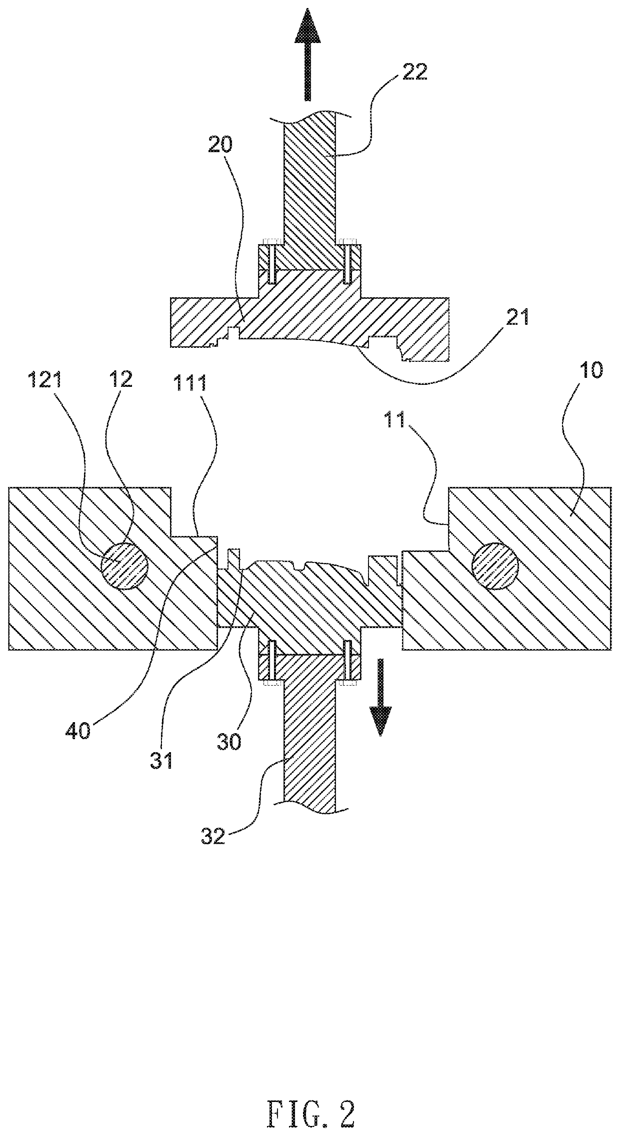
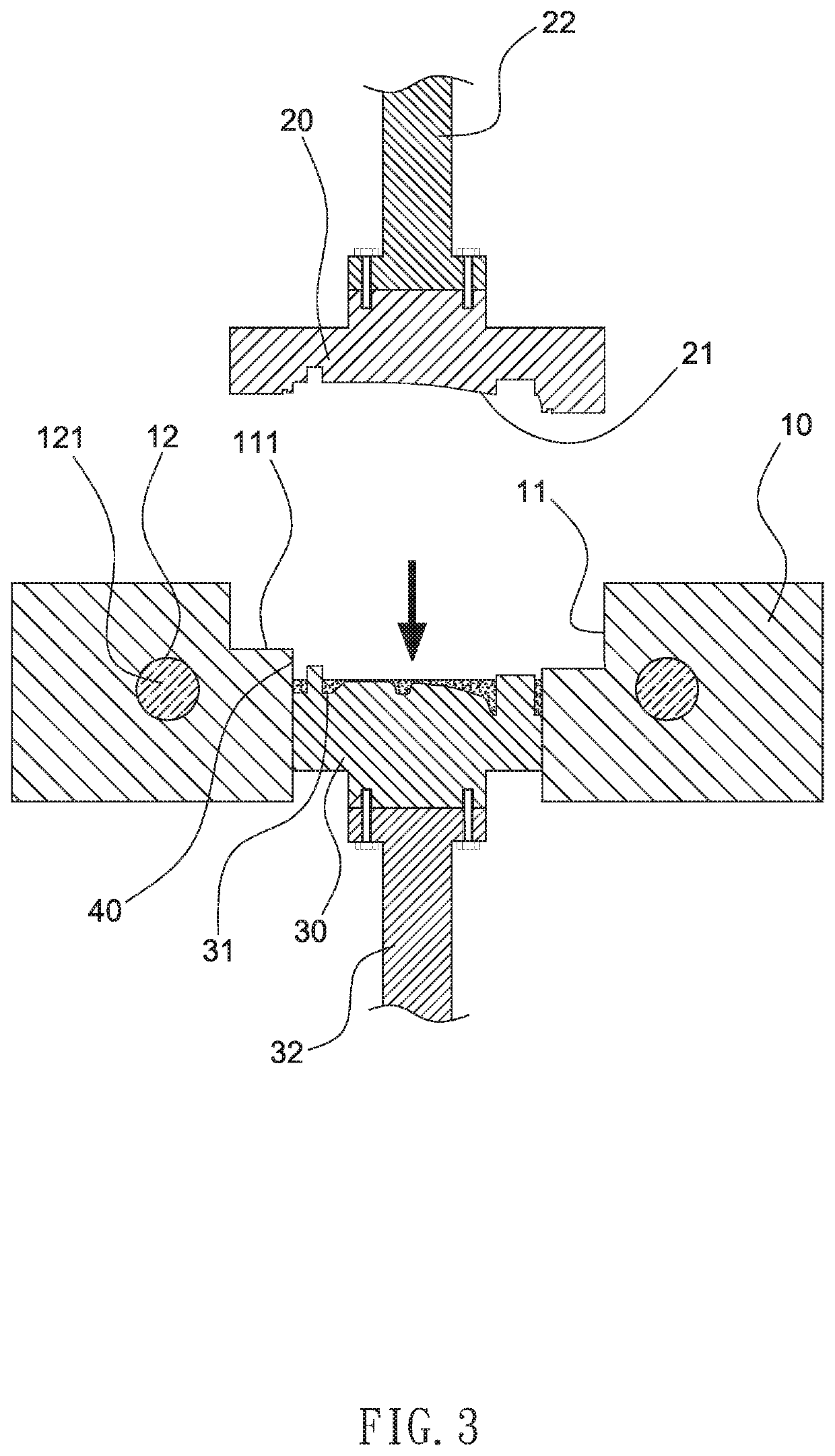
[0021]Referring to FIG. 1 to FIG. 8, the present invention discloses a forging device for molten metal, comprising a die base 10. The die base 10 has a cavity 11 therein. A first die body 20 and a second die body 30 are sequentially disposed in the cavity 11.

[0022]One end of the first die body 20 has a first die face 21. (It can be changed according to actual needs). Another end of the first die body 20 is locked by a screw to a first power arm 22. (The first power arm 22 is a hydraulic push rod or a screw rod driven by a hydraulic cylinder.)

[0023]One end of the second die body 30 has a second die face 31 opposite to the first die face 21. (According to actual needs, it can be modified relative to the first die face 21). Another end of the second die body 30 is locked by a screw to a second power arm 32. (The second power arm 32 is a hydraulic push ro...


PUM

PropertyMeasurementUnit
Strengthaaaaaaaaaa

Abstract

A forging device for molten metal includes first and second die bodies that are linked by first and second power arms to move back and forth in a cavity of a die base so as to open and close a workpiece shaping space defined between first and second die faces of the first and second die bodies. When the workpiece shaping space is opened, a molten metal is poured, and then the workpiece shaping space is closed to cast a semi-finished workpiece. After that, the first and second power arms axially press and forge the semi-finished workpiece in the workpiece shaping space into a high-strength workpiece. The high-strength workpiece is shaped by casting and forging in the same process.

Description

FIELD OF THE INVENTION[0001]The present invention relates to a forging device for molten metal, and more particularly to a forging device that can produce a high-strength workpiece by casting and forging in the same process.BACKGROUND OF THE INVENTION[0002]A conventional high-strength workpiece is first manufactured by casting to form a semi-finished product, and then the semi-finished product is pressurized by forging to form a workpiece with high strength. However, the semi-finished product before forging is usually placed in a forging die by manpower, robotic arm or automatic feeding equipment, which needs to be aligned or calibrated. Then, the semi-finished product is forged by a forging machine. The above two processes cost a lot of equipment, labor and time, and the precision of the finished product is poor (there will be a misalignment of the parting line), resulting in poor economic benefits of the above-mentioned conventional processes. Accordingly, the inventor of the pres...

Claims


Application Information

Patent Timeline
IPC IPC(8): B21J7/28B21J13/03B21J1/06
CPCB21J7/28B21J1/06B21J13/03B21J5/002B21J5/025B21J13/02B21K5/16B21J5/02
Inventor HSU, CHARLESHSU, CHIN-HSIANGHSU, CHEN-CHE
Owner JOIN YIUH IND
Why Eureka
Try Eureka