Liner configuring member, high pressure tank, and method of manufacturing same

Active Publication Date: 2020-03-19
HONDA MOTOR CO LTD
View PDF0 Cites 2 Cited by
  • Summary
  • Abstract
  • Description
  • Claims
  • Application Information

AI Technical Summary

Benefits of technology

The present invention provides a liner configuring member that can be joined to create a high pressure tank that is reliable and secure. The liner configuring member has flange sections that can be joined to increase the abutting area and create a strong joining section. By manufacturing the liner configuring members individually and aligning them sequentially, a high pressure tank with excellent pressure tightness and prevention of leakage can be obtained. The liner configuring member can be easily obtained by injection molding, and the mold can be opened along the longitudinal direction of the liner configuring member for further manufacturing.

Problems solved by technology

In the case of obtaining a large and long resin product, if an injection molding apparatus of small injection power is employed, then it becomes difficult for a molten resin to be made to reach to corner sections of a molding cavity of the mold, and there is a possibility of a filling defect (a so-called short) occurring in a flow length tip.
Moreover, even if a short is not reached, it becomes difficult to obtain a liner configuring member having good dimensional accuracy, that is, good flatness, of its welding region, due to there not being obtained sufficient filling density in the flow length tip.
Therefore, an enormous and expensive injection molding apparatus of extremely large maximum injection power becomes required.
Moreover, highly precisely manufacturing a mold for forming a long cavity leads to a rise in costs.
In this case, although open ends of the liner configuring members are joined by being abutted on each other, the open ends are thin, so, even though a contribution is made to lightening weight, it is not easy for a sufficient joining force to be given to an abutting place.

Method used


Image

  • Liner configuring member, high pressure tank, and method of manufacturing same
  • Liner configuring member, high pressure tank, and method of manufacturing same
  • Liner configuring member, high pressure tank, and method of manufacturing same

Examples


first embodiment

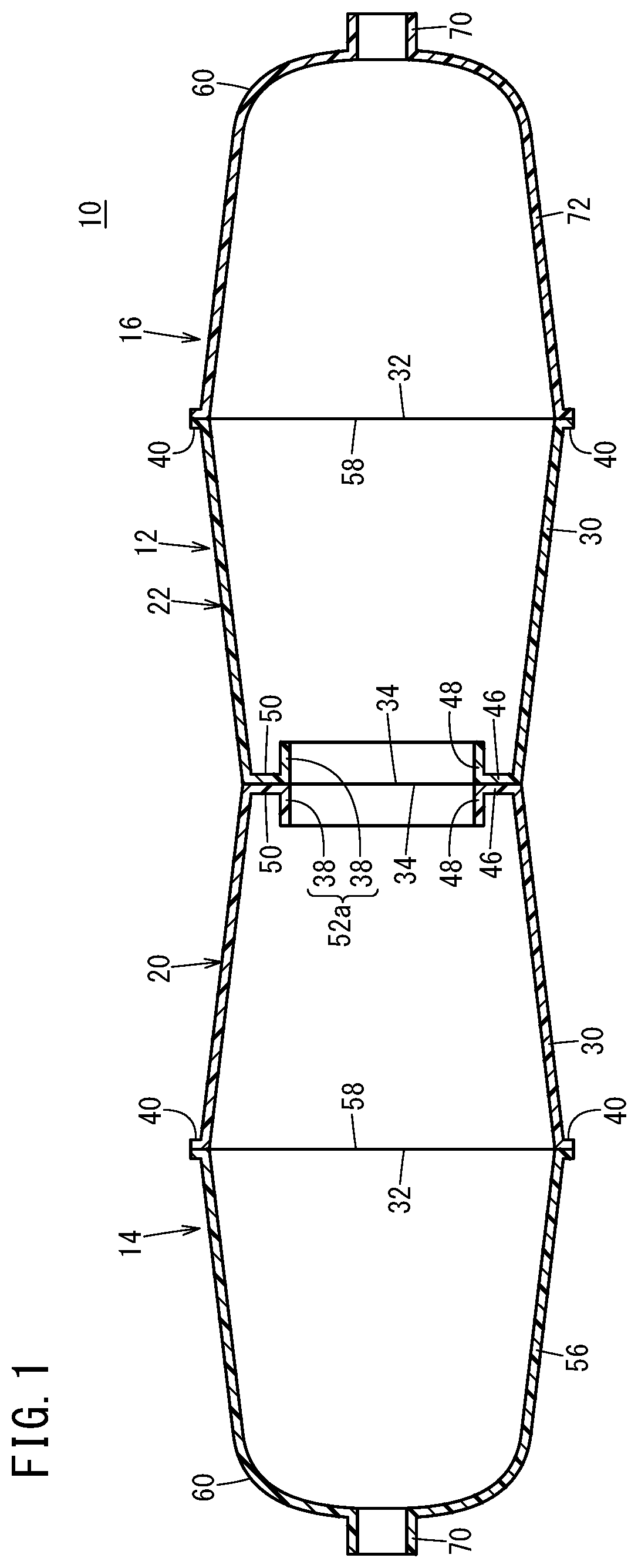
[0035]FIG. 1 is a schematic side cross-sectional view of a resin liner (hereafter, written also simply as “liner”) 10 configuring a high pressure tank according to a This liner 10 includes: a trunk section 12; and a first blocking section 14 and a second blocking section 16 that block both ends of the trunk section 12.

[0036]The trunk section 12 is configured by a first trunk section configuring member 20 and a second trunk section configuring member 22 being joined. Although the first trunk section configuring member 20 and the second trunk section configuring member 22 are liner configuring members having substantially the same shape as each other, in order to clearly distinguish members 20, 22 from each other, different reference symbols are assigned to the members 20, 22.

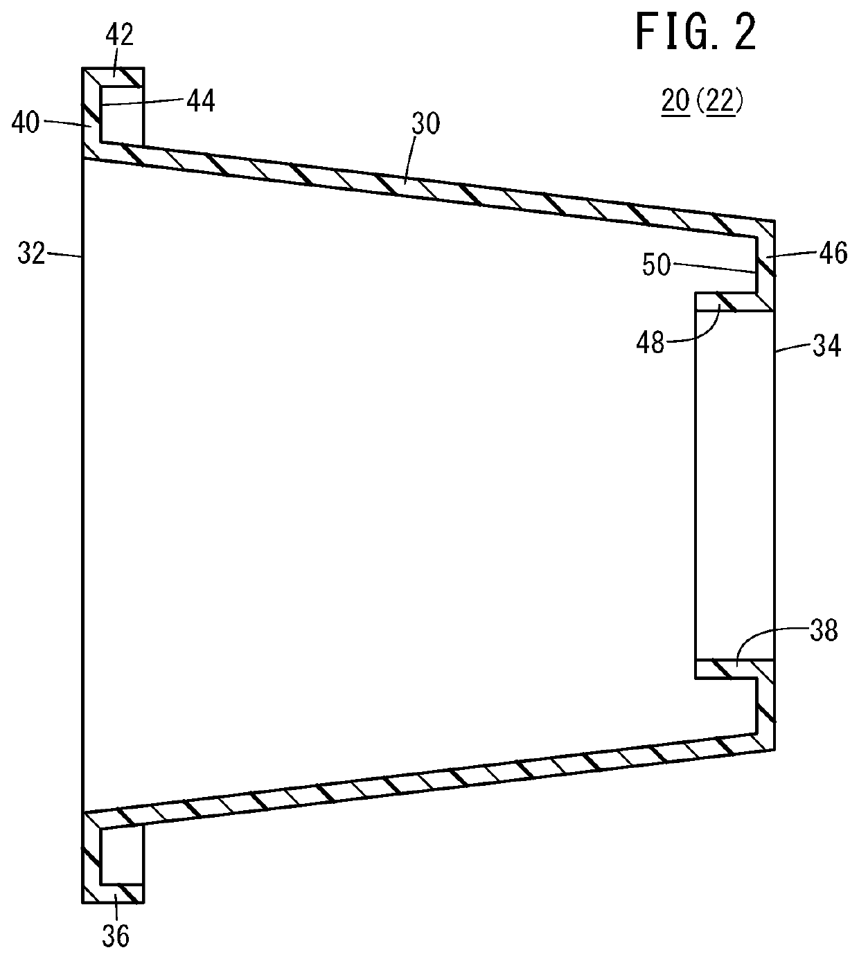
[0037]First, the first trunk section configuring member 20 and the second trunk section configuring member 22 will be described. FIG. 2 is a schematic side cross-sectional view of the first trunk section configu...

second embodiment

[0063]Note that a different one from the vibration welding-dedicated jigs 80a, 80b for joining the first trunk section configuring member 20 and the second trunk section configuring member 22 may be used as a vibration welding-dedicated jig for joining the first trunk section configuring member 20 and the first blocking member 56. Although this applies similarly also in a later-mentioned second embodiment, hereafter, description will be made exemplifying the case where the same vibration welding-dedicated jigs 80a, 80b are used.

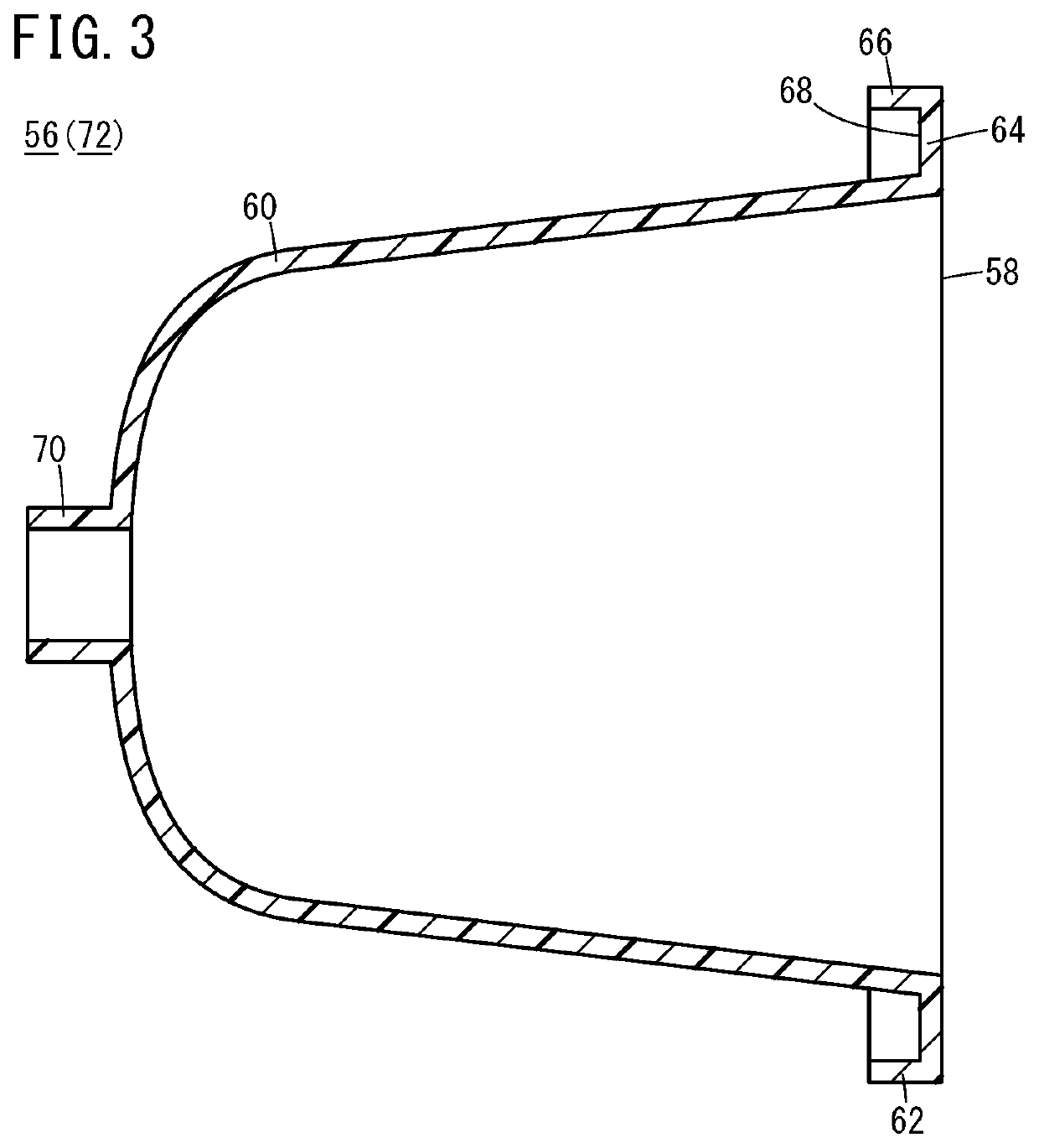
[0064]Vibration welding is performed hereafter similarly to the one described above. That is, the vibration welding-dedicated jigs 80a, 80b are displaced whereby the third flange section 62 of the first blocking member 56 and the first flange section 36 of the first trunk section configuring member 20 are pressed in a direction of approaching each other. As a result, the third open end 58 of the first blocking member 56 and the first open end 32 of the first ...


PUM

PropertyMeasurementUnit
Pressureaaaaaaaaaa
Diameteraaaaaaaaaa

Abstract

A liner configuring member configuring a liner includes a main body section which is configured from a resin material and has both ends opened. That is, both ends of the main body section are, respectively, a first open end and a second open end. There is provided in a vicinity of the first open end a first flange section where a first annular recess is formed by a first bottom section and a first side section. On the other hand, there is provided in a vicinity of the second open end a second flange section where a second annular recess is formed by a second bottom section and a second side section.

Description

CROSS-REFERENCE TO RELATED APPLICATION[0001]This application is based upon and claims the benefit of priority from Japanese Patent Application No. 2018-172376 filed on Sep. 14, 2018, the contents of which are incorporated herein by reference.BACKGROUND OF THE INVENTIONField of the Invention[0002]The present invention relates to a liner configuring member that configures a high pressure tank for storing a high pressure gas, relates to a high pressure tank which has a liner that includes the liner configuring member, and relates to a method of manufacturing the high pressure tank.Description of the Related Art[0003]A high pressure tank is provided in a vehicle-installed fuel cell system and stores a hydrogen gas to be supplied to an anode, for example. This type of high pressure tank has a resin liner which is configured from the likes of a thermoplastic resin material having hydrogen barrier properties. Conventionally, the resin liner is manufactured by liner configuring members of s...

Claims


Application Information

Patent Timeline
IPC IPC(8): F17C1/16
CPCF17C1/16F17C2203/0604F17C2221/012F17C2201/0109F17C2203/0614F17C2203/066F17C2205/0305F17C2270/0184F17C13/002F17C1/06H01M8/04201F17C2201/056F17C2203/0663F17C2223/0123F17C2223/035F17C2223/036F17C2209/234F17C2209/23F17C1/00F17C2201/0123F17C2201/054F17C2203/0619F17C2203/0658F17C2209/2127F17C2209/232F17C2209/221F17C2209/2154F17C2270/0171F17C2270/0176Y02E60/32Y02E60/50
Inventor WATANABE, HIDEOSATO, TAKAHARU
Owner HONDA MOTOR CO LTD
Why Eureka
Try Eureka