a hip prosthesis

A hip joint prosthesis and acetabular technology, applied in the field of hip joint replacement, can solve the problems of increasing patient pain, small sidewall compression, wear of acetabular lining, etc., and achieve the effect of reducing the difficulty of surgery

Active Publication Date: 2021-07-27
天衍医疗器材有限公司
View PDF18 Cites 0 Cited by
  • Summary
  • Abstract
  • Description
  • Claims
  • Application Information

AI Technical Summary

Problems solved by technology

However, there are also some defects in the existing hip replacement surgery. First, one of the most concerned issues in the industry is the problem of particles produced by the wear of the acetabular lining. Most of the existing acetabular linings are made of ultra-high molecular weight polyethylene materials. Manufacture, after installing the prosthesis, most of the movement friction occurs between the ball head and the acetabular lining. The wear rate of the metal ball head is extremely low, about 0.00400 / year, while the wear rate of polyethylene is 0.1mm / year , the particles produced by polyethylene wear can lead to a series of case reactions such as synovitis, joint instability, osteolysis and prosthesis loosening; In the human acetabular fossa, the acetabular outer cup is fixed on the human acetabular fossa with screws. During this process, the acetabular outer cup is prone to deflection, causing the acetabular outer cup to not be accurately installed. If the installation is misplaced, it needs to be re-drilled. Hole installation will increase the risk of surgery and increase the pain of the patient; 3. During the operation, in order to match the acetabular socket and the acetabular cup, it is necessary to use a file to grind the acetabular socket to fit the acetabular cup However, the natural shape of the human acetabular fossa is that the side wall is thicker and the bottom is thinner. The force of press-fitting between the acetabular fossa and the acetabular outer cup should gradually decrease from the side wall to the bottom. In the prior art The press-fitting force of the acetabular fossa and the acetabular cup will lead to excessive bone compression at the bottom of the acetabular fossa and too little compression of the side wall

Method used


Image

  • a hip prosthesis
  • a hip prosthesis
  • a hip prosthesis

Examples


Embodiment

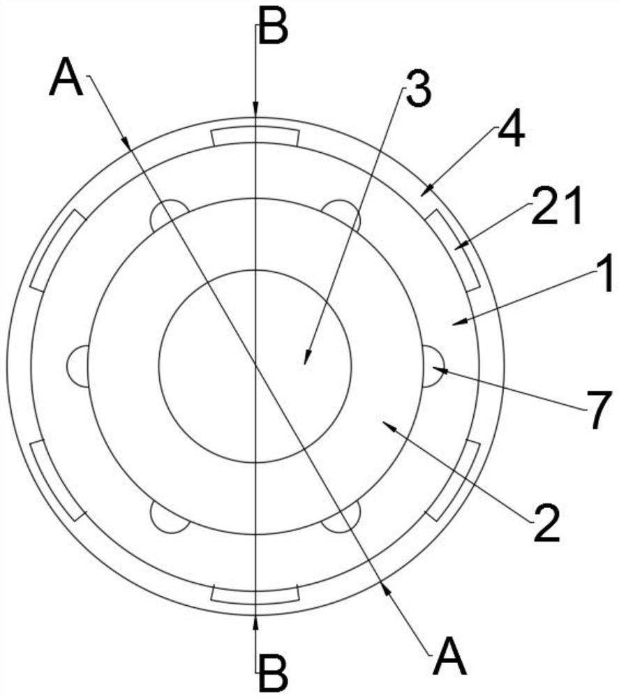
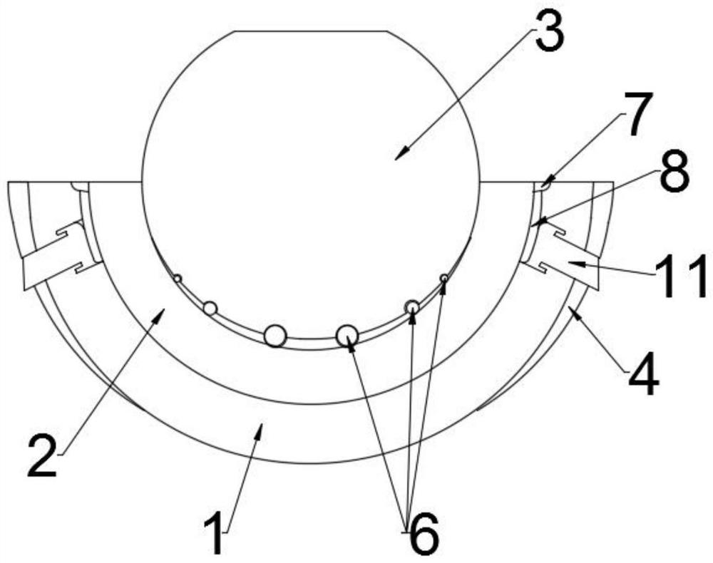
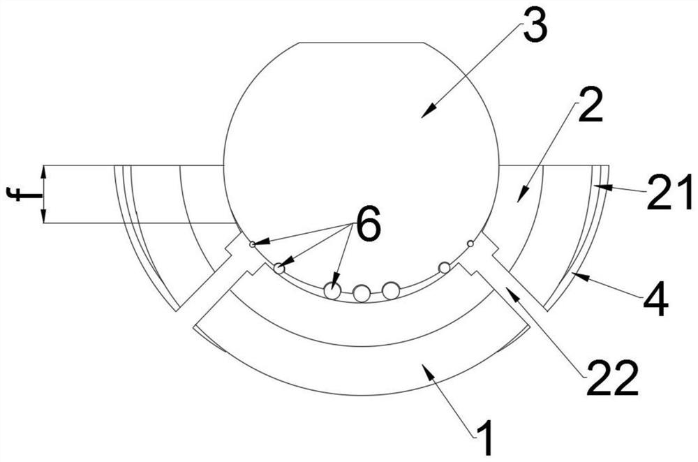
[0032] Example: see Figure 1-14 , in the present invention, a hip joint prosthesis includes an acetabular outer cup 1, an acetabular lining 2, and a ball head 3. The acetabular outer cup 1 is a hemisphere for placing in the acetabular fossa of a human body, and the traditional acetabular cup The outer cup is the same, the acetabular lining 2 is a hemisphere, the same as the traditional acetabular lining, made of ultra-high molecular polyethylene material, the ball head 3 is an irregular sphere, the same material as the traditional ball head, the ball head 3 in the shape of Figure 4 As shown, wherein the hypothetical line 23 does not exist, the hypothetical line 23 is a line of a regular sphere, the shape of the lower end of the ball head 3 is an ellipsoid, and the outer side of the acetabular cup 1 is provided with a thickened cover 4, which is Hemispherical annular structure with an open lower end, namely Figure 12 As shown, the acetabular lining 2 is located inside the ac...


PUM


Abstract

The invention discloses a hip joint prosthesis, which comprises an acetabular outer cup, an acetabular inner liner and a ball head; , the ball head is located inside the acetabular lining, and the lower end of the ball head in contact with the acetabular lining is provided with several hemispherical grooves, and balls are arranged in the hemispherical grooves, and the balls and the acetabular lining The upper end of the outer wall of the acetabular lining is in contact with the inner wall. Several petal protrusions are arranged around the upper end of the outer wall of the acetabular lining. The lower end of the petal protrusions is provided with strip-shaped protrusions. A special-shaped square hole is provided, a square hole is provided on the side wall of the thickened sleeve corresponding to the special-shaped square hole, and a special-shaped movable block is arranged in the special-shaped square hole and the square hole. The hip joint prosthesis disclosed by the invention reduces the friction between the acetabular lining and the ball head, and can pre-fix the acetabular outer cup when installing the acetabular outer cup, reducing the risk of installation failure.

Description

technical field [0001] The invention relates to the field of hip joint replacement, in particular to a hip joint prosthesis. Background technique [0002] The human hip joint is composed of the femoral head and the acetabular socket. It is a typical acetabular joint and is located at the root of the human thigh. Walking, can only rest in bed, at this time you need to do hip replacement surgery, that is, use hip prosthesis to replace the human hip joint, instead of hip joint movement, the existing hip joint replacement surgery has been developed for more than 100 years. Quite mature, benefiting many patients with femoral head necrosis. However, there are also some defects in the existing hip replacement surgery. First, one of the most concerned issues in the industry is the problem of particles produced by the wear of the acetabular lining. Most of the existing acetabular linings are made of ultra-high molecular weight polyethylene materials. Manufacture, after installing t...

Claims


Application Information

Patent Timeline
Patent Type & Authority Patents(China)
IPC IPC(8): A61F2/32A61F2/34
CPCA61F2/32A61F2/34A61F2002/3412A61F2002/3429A61F2002/3453A61F2002/3483
Inventor 王秀芳
Owner 天衍医疗器材有限公司
Why Eureka
Try Eureka