
High-pressure oil supply pump oil pumping system assembly of large-flow electric control common rail system

A technology of common rail system and large flow, which is applied in the direction of charging system, engine components, fuel injection pump, etc., and can solve the problems of failure to meet the requirements of high rail pressure and large flow, failure of high-pressure fuel supply pump, and failure of common rail system and other issues to achieve the effect of improving reliability and response speed, compact structure and high reliability

Pending Publication Date: 2022-04-05
龙口龙泵柴油喷射高科有限公司
View PDF0 Cites 0 Cited by
  • Summary
  • Abstract
  • Description
  • Claims
  • Application Information

AI Technical Summary

Problems solved by technology

The damage and failure of the pump oil system components will directly cause the failure of the high-pressure oil supply pump, and then cause the failure of the entire common rail system
The high-pressure oil supply pumps of the existing domestically-made electronically controlled common rail systems are mostly used in small and medium-sized diesel engines, and the components of the pump oil system cannot meet the requirements of high-power diesel engines for high rail pressure and large flow

Method used


Image

  • High-pressure oil supply pump oil pumping system assembly of large-flow electric control common rail system
  • High-pressure oil supply pump oil pumping system assembly of large-flow electric control common rail system
  • High-pressure oil supply pump oil pumping system assembly of large-flow electric control common rail system

Examples


Embodiment Construction

[0030] Attached below Figure 1-5 , clearly and completely describe the technical solutions in the embodiments of the present invention, obviously, the described embodiments are only some of the embodiments of the present invention, not all of them. Based on the embodiments of the present invention, all other embodiments obtained by persons of ordinary skill in the art without making creative efforts belong to the protection scope of the present invention.

[0031] In describing the present invention, it should be understood that the terms "longitudinal", "transverse", "upper", "lower", "front", "rear", "left", "right", "vertical", The orientations or positional relationships indicated by "horizontal", "top", "bottom", "inner", "outer", etc. are based on the orientations or positional relationships shown in the drawings, and are only for the convenience of describing the present invention, rather than indicating or It should not be construed as limiting the invention by imply...


PUM


Abstract

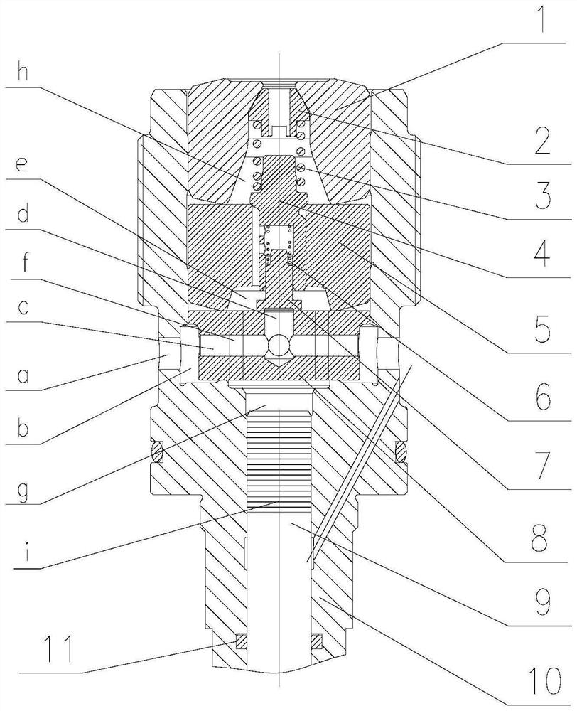
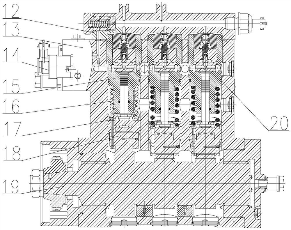
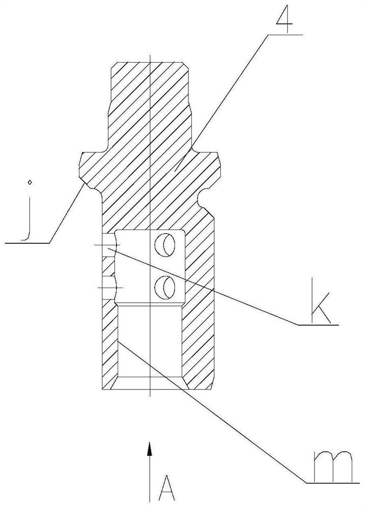
The invention discloses a high-pressure oil feed pump oil pumping system assembly of a large-flow electric control common rail system, which comprises a plunger and barrel assembly, an oil inlet mechanism and an oil outlet mechanism, the plunger and barrel assembly comprises a plunger and a plunger sleeve, the plunger sleeve is a main body of the whole oil pumping system assembly, the upper part of the plunger sleeve is provided with a cavity, and the lower part of the plunger sleeve is provided with a plunger sleeve cavity g; the plunger is installed in a plunger sleeve cavity g, the plunger sleeve and the plunger form a precise matching part structure and are in clearance fit, the bottom of the plunger is installed on the spring seat, the oil inlet mechanism and the oil outlet mechanism are both installed in a cavity in the upper portion of the plunger sleeve, the oil outlet mechanism is located above the oil inlet mechanism, and the oil outlet mechanism is located above the oil outlet mechanism. The plunger sleeve is connected with the top of the plunger spring, and a plurality of first oil inlet holes a are formed in the outer wall of the periphery of the upper cavity part of the plunger sleeve. The oil pumping system assembly is compact in structure, large in oil quantity and oil flow speed and high in reliability, and the requirements of a high-power diesel engine for high rail pressure and large oil quantity are met.

Description

technical field [0001] The invention belongs to the technical field of oil supply pumps for high-power diesel engines, and in particular relates to a high-pressure oil supply pump oil system component of a large-flow electronically controlled common rail system. Background technique [0002] The pump oil system component is the key component of the high-pressure fuel supply pump of the electronically controlled common rail system. Its function is to pressurize the diesel oil from the low-pressure chamber of the fuel supply pump and press the high-pressure diesel oil into the rail body components. Pump oil system components are generally composed of plunger couplings, oil inlet flat valve parts, oil outlet valve couplings, oil inlet valve springs, oil outlet valve springs, spring upper seats, tight seats and other components; Plane valve components and oil outlet valve couplers are the key components of the pump oil system components; their size structure and material propert...

Claims


Application Information

Patent Timeline
IPC IPC(8): F02M59/36F02M59/44F02M59/46F02M55/02
Inventor 杨明亮刘本学赵华来贾玉杰张海涛郭文华蒋金喜
Owner 龙口龙泵柴油喷射高科有限公司
Learn More