
Method for epipolar time of flight imaging

a flight imaging and epipolar technology, applied in the field of flight imaging methods, can solve the problems of photon noise, limited power consumption and eye safety considerations of cw-tof sensors, and low energy efficiency of cw-tof sensors, so as to minimize motion blur, minimize motion artifacts and depth errors, and avoid camera shake.

Active Publication Date: 2020-03-19
CARNEGIE MELLON UNIV +1
View PDF0 Cites 5 Cited by
  • Summary
  • Abstract
  • Description
  • Claims
  • Application Information

AI Technical Summary

Benefits of technology

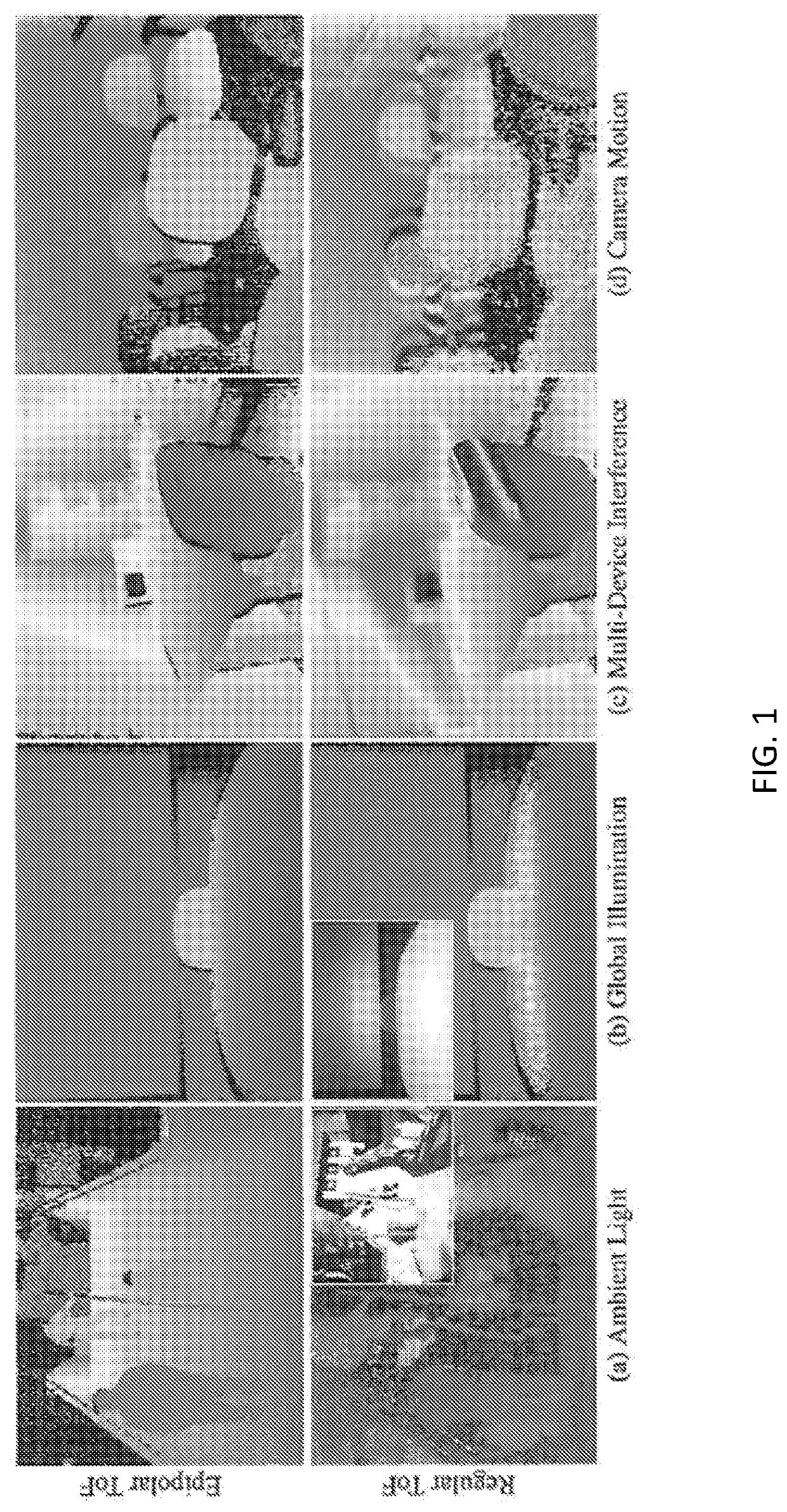
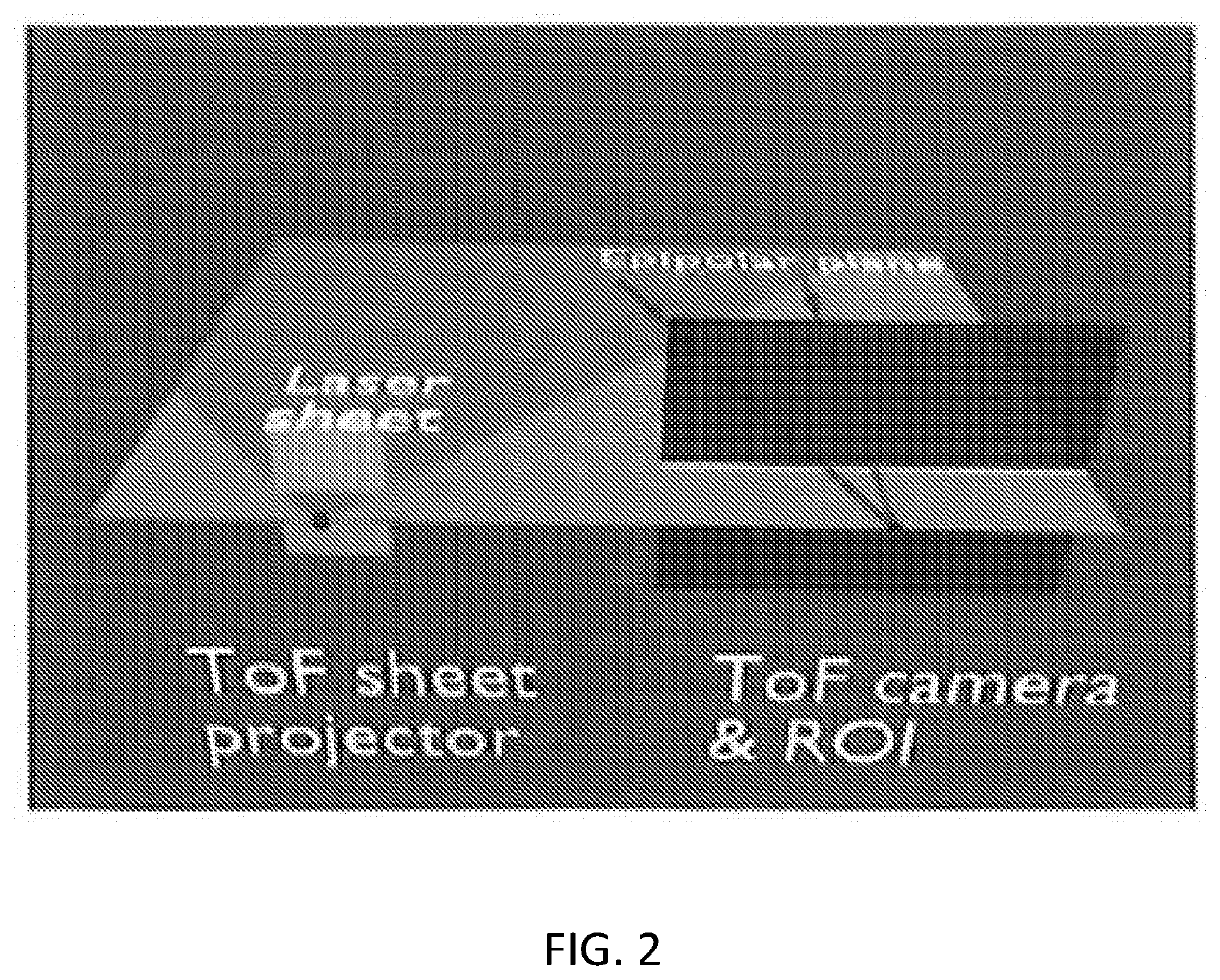
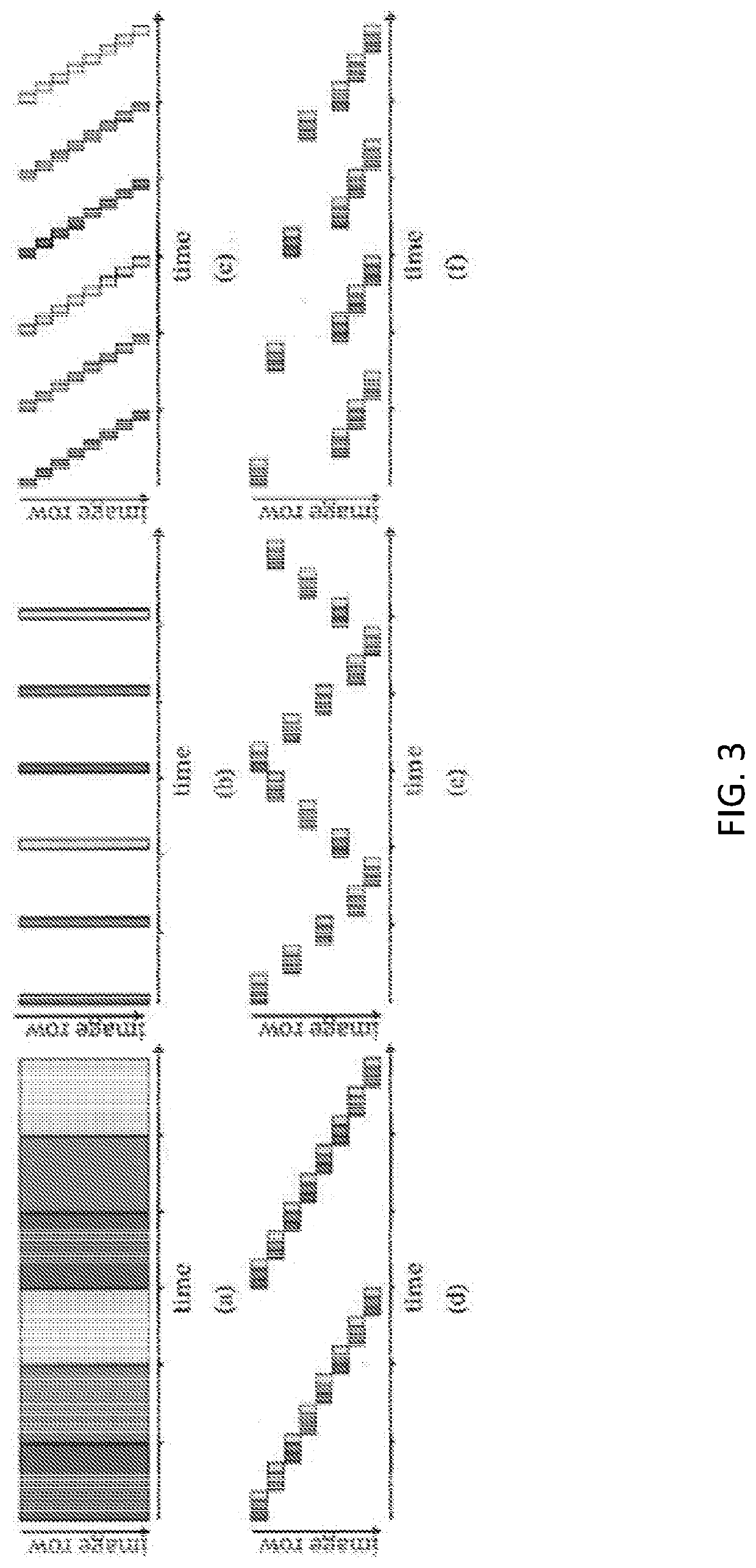
The present invention uses energy-efficient epipolar imaging to overcome the shortcomings of CW-ToF. A continuously-modulated sheet of laser light is projected along a sequence of carefully chosen epipolar planes that collectively span the field of view. Only a strip of CW-ToF pixels corresponding to each epipolar plane is exposed, minimizing motion blur and depth errors. Epipolar ToF makes it easier to address both problems by acquiring multiple phase measurements per epipolar plane and scheduling the sequence of epipolar planes so that post-acquisition distortion correction becomes easier.

Problems solved by technology

The approach has been extended to the ToF domain, but its energy efficiency is very low and it involves capturing more than 500 images to calculate a single “direct-only” ToF image.
The primary difficulty is that the range of CW-ToF sensors is severely limited by power consumption and eye safety considerations.
Although most CW-ToF sensors electronically subtract the DC component of incident light, photon noise from strong ambient sources such as sunlight can easily overwhelm the CW-ToF signal at distances of more than a few meters outdoors at typical frame rates.
A secondary difficulty is that the depth accuracy of CW-ToF sensors is strongly affected by global illumination effects, such as inter-reflections and global illumination transport.
These effects produce longer light paths and show up as a source of structured additive noise.

Method used


Image

  • Method for epipolar time of flight imaging
  • Method for epipolar time of flight imaging
  • Method for epipolar time of flight imaging

Examples


Embodiment Construction

[0020]The term microcontroller, as used herein, may mean a dedicated hardware device, circuitry, an ASIC, an FPGA, a microprocessor running software, or any other means known in the art. It is further understood that the microcontroller will include connections to both the sensor and the laser light projector for sending control signals, and for receiving data. The invention is not intended to be limited to one method of implementing the functions of the controller.

[0021]As used herein, the terms camera and sensor are used interchangeably.

Continuous Wave Time of Flight

[0022]CW-ToF cameras use a temporally modulated light source and a sensor where the exposure is also modulated during integration. If the illumination modulation function is fωt=cos(ωt) and the sensor modulation function is gω,ϕ(t)=cos(ωt+ϕ) where ω is the modulation frequency in rad / s and ϕ is the phase offset between the source and sensor modulation functions, then the measurement at a pixel x is:

Iω,σ(x)=∫oTfω(t)*[hx...


PUM


Abstract

Energy-efficient epipolar imaging is applied to the ToF domain to significantly expand the versatility of ToF sensors. The described system exhibits 15+ m range outdoors in bright sunlight; robustness to global transport effects such as specular and diffuse inter-reflections; interference-free 3D imaging in the presence of many ToF sensors, even when they are all operating at the same optical wavelength and modulation frequency; and blur- and distortion-free 3D video in the presence of severe camera shake. The described embodiments are broadly applicable in consumer and robotics domains.

Description

RELATED APPLICATIONS[0001]This application claims the benefit of U.S. Provisional Patent Application Ser. No. 62 / 499,193, filed Jan. 20, 2017.GOVERNMENT RIGHTS[0002]This invention was made with government support under N000141512358 awarded by the ONR, 11S1317749 awarded by the NSF, HR00111620021 awarded by DARPA, and grants NNX16AD98G and NNX14AM53H awarded by NASA. The government has certain rights in the invention.BACKGROUND OF THE INVENTION[0003]Time-of-flight (ToF) depth sensors have become the technology of choice in diverse applications, from automotive and aviation to robotics, gaming and consumer electronics. These sensors come in two general flavors: LIDAR-based systems that rely on extremely brief pulses of light to sense depth, and continuous-wave (CW) systems that emit a modulated light signal over much longer duration. The LIDAR-based systems can acquire centimeter-accurate depth maps up to a kilometer away in broad daylight, but have low measurement rates. Additionall...

Claims


Application Information

Patent Timeline
Patent Type & Authority Applications(United States)
IPC IPC(8): H04N13/254H04N13/296H04N13/211G01S7/4914G01S17/894
CPCG01S17/894G01S7/4914H04N13/254H04N13/211H04N13/296G01S7/4814G01S7/4817H04N13/271H04N13/246
Inventor NARASIMHAN, SRINIVASAACHAR, SUPREETHKUTULAKOS, KIRIAKOSBARTELS, JOEWHITTAKER, WILLIAM
Owner CARNEGIE MELLON UNIV
Learn More