Method and an arrangement for removing stretch in polyester mooring lines with an inline tensioner

a technology of stretch and tensioner, which is applied in the direction of anchoring arrangement, waterborne vessel, vessel parts, etc., can solve the problems of increasing the cost of using a support vessel every time, affecting the service life of the support vessel, so as to avoid additional weight and less weight

Active Publication Date: 2020-03-26
SEASYSTEMS AS
View PDF4 Cites 0 Cited by
  • Summary
  • Abstract
  • Description
  • Claims
  • Application Information

AI Technical Summary

Benefits of technology

[0024]The invention also has an objective to avoid additional weight midwater on the mooring line from the chain stopper structure and the excess mooring chain. A wire sheave or only a coupling positioned mid-water has considerable less weight

Problems solved by technology

In this period between installation and next operation, the equipment has normally seized or corroded and requires refurbishment.
When a new polyester mooring line is tensioned, it tends to elongate over time due to visco-elastic stretch and permanent unrecoverable stretch.
In a permanent mooring system on a floating unit with a riser system and/or drill string, this may be a problem if the elongation of the polyester causes the vessel to move outside the acceptable excursion c

Method used


Image

  • Method and an arrangement for removing stretch in polyester mooring lines with an inline tensioner
  • Method and an arrangement for removing stretch in polyester mooring lines with an inline tensioner
  • Method and an arrangement for removing stretch in polyester mooring lines with an inline tensioner

Examples


first embodiment

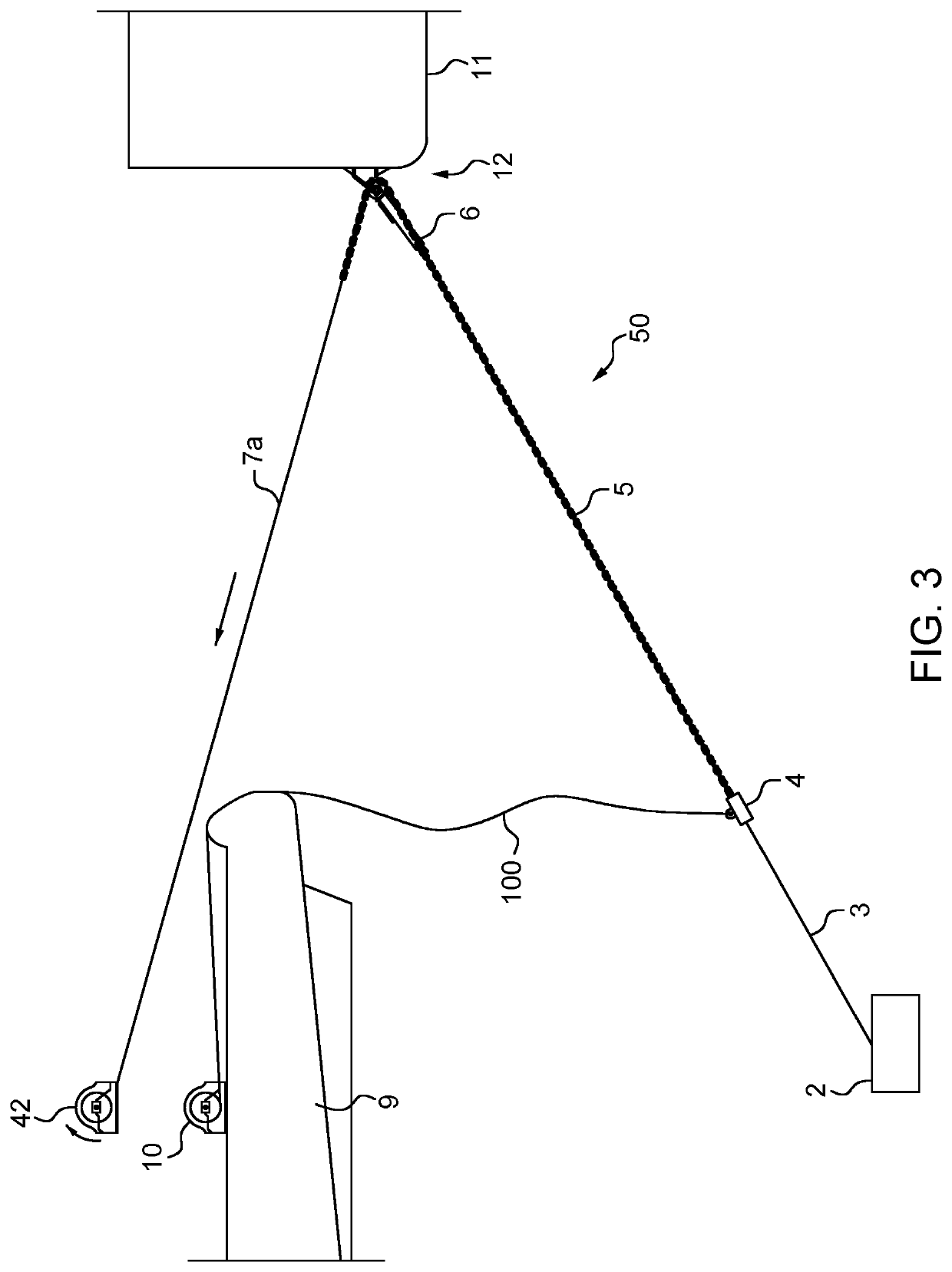
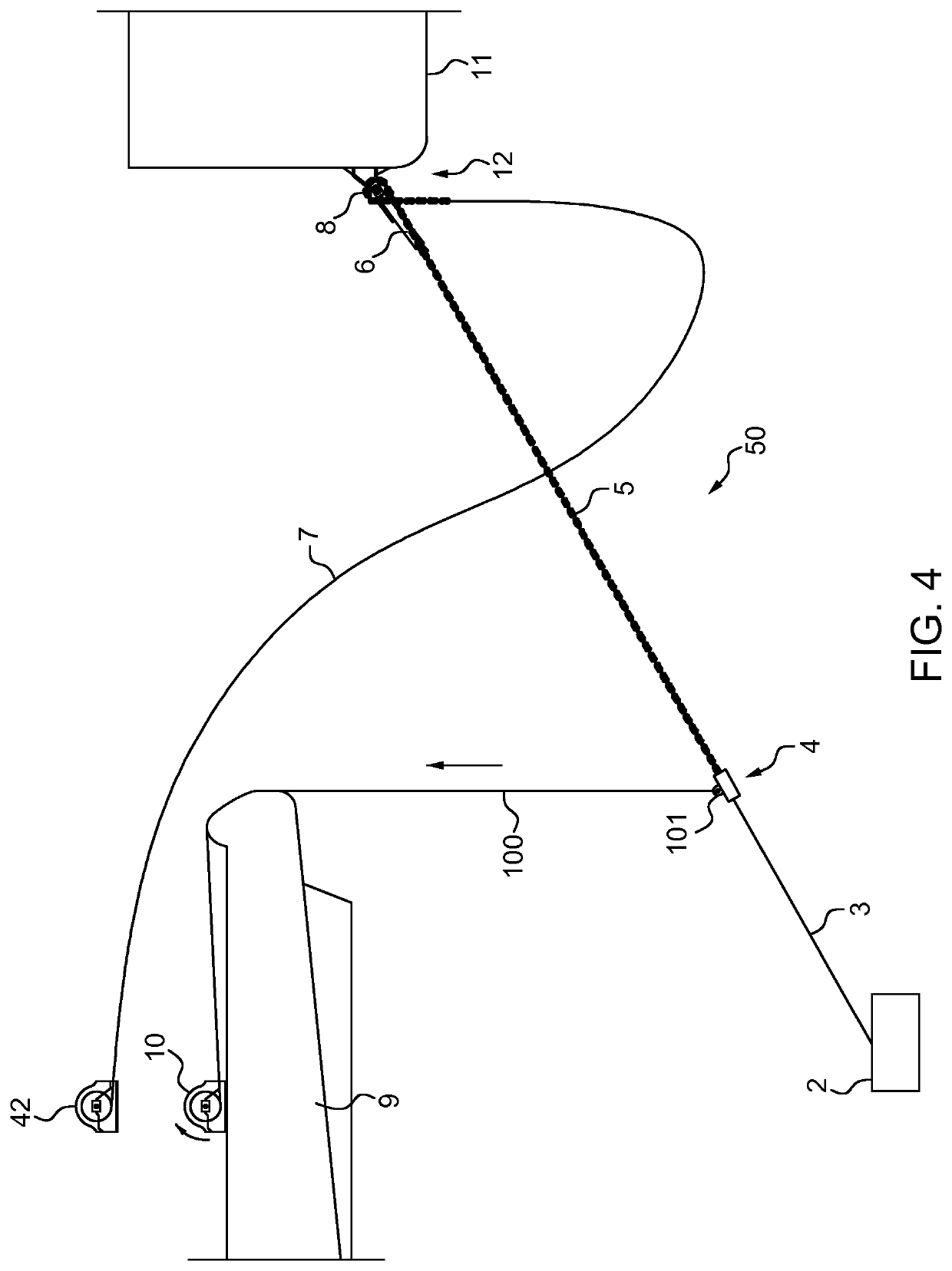
[0064]FIGS. 3 and 4 shows the inline tensioner according to the invention. In this embodiment, the pretension can reach a pretension level of 1× bollard pull of an installation vessel 9 as will be further described.

[0065]FIG. 3 shows the arrangement for pre-tensioning a mooring line up to a pretension level.

[0066]A tensioning mooring arrangement 50 is installed between an anchor 2 that has been attached to the seabed 1 and a floating structure 11, such as an FPSO. This installation is further performed by help of an installation vessel or a pulling unit 9.

[0067]The anchor 2 is conveniently a suction anchor, but it may alternatively be any type of anchor known in the field.

[0068]The pre-tensioning mooring arrangement 50 further comprises a mooring line 3, a midwater coupling 4 and a chain stopper arrangement 12.

[0069]The term midwater coupling 4 is to be interpreted broadly and not as an indication that the midwater coupling 4 has to be positioned midwater. The term indicates that th...

second embodiment

[0097]FIGS. 5 and 6 discloses the inline tensioner according to the invention. In this embodiment, the pretension can reach a pretension level of 3× bollard pull of the installation vessel 9 as will be further described below. This means that the arrangement of the pretension arrangement results in a tensioning force from the installation vessel up to three times higher than the arrangement shown in FIG. 3-4.

[0098]FIG. 5 shows the arrangement for the pre-tensioning the mooring line 3 up to the pre-tension level obtained by the installation vessel 9.

[0099]In addition to the pretension arrangement 50 as disclosed in the first embodiment in FIGS. 3 and 4, the pretension mooring arrangement 51 in this embodiment further comprises a midwater coupling 40 having a midwater pulley 20. There is also arranged a wire pulley 16 on the floating structure 11. The wire pulley 16 is preferably arranged on the hull of the floating structure 11 above the chain stopper arrangement 12.

[0100]The mooring...

third embodiment

[0107]FIGS. 7 and 8 discloses the inline tensioner according to the invention. In this embodiment, the pretension can reach a pretension level of 2× bollard pull of the installation vessel 9 as will be further described below.

[0108]This means that the arrangement of the pretension arrangement 52 results in a tensioning force from the installation vessel 9 up to two times higher than the arrangement shown in FIG. 3-4.

[0109]FIG. 7 shows the arrangement for the pre-tensioning the mooring line 3, 5, 7 up to the pretension level.

[0110]In this embodiment the mooring line 3, 5, 7 have a different arrangement than in the previous embodiments.

[0111]The mooring rope 3 extending between the anchor 2 and a midwater coupling 400.

[0112]In the FIG. 7 there is shown a pedant wire 5a attached to the floating structure 11. The pedant wire 5a is attached to the floating structure through a fairlead arrangement 120 that is attached to the hull of the floating structure 11. The other end of the pendant ...


PUM


Abstract

The invention relates to a mooring tensioning arrangement for a floating structure or a vessel (11), comprising -a mooring line (3, 5, 7) having a first mooring part (3) and a second mooring part (5, 7), divided by a midwater coupling (4, 40, 400, 111), said at least a portion of the mooring line (3, 5, 7) is made of synthetic material, -said mooring line (3, 5, 7) is extending between an anchor (2) arranged on the seabed and a pulling unit (9, 10, 42) arranged separate from the floating structure or vessel (11), said mooring line (3, 5, 7) is extending at least via a fairlead pulley or a chain wheel (8, 80) arranged on the floating structure (11) between the anchor and the pulling unit (9, 10, 42) when the mooring line (3, 5, 7) being pre-tensioned, -a chain stopper (6, 60) being arranged in connection with the mooring line (3, 5, 7) between the anchor (2) and the floating vessel or structure (11) for tensioning the part of the mooring line (3, 5, 7) situated between the floating structure (11) and the anchor (2) at a pretension level. The mooring tensioning arrangement further comprising a second tensioning line (100) configured to be attached in one end to the midwater coupling (4, 40, 400) and in the other end coupled to the pulling unit (9,10, 42) when said mooring line (3, 5, 7) being re-tensioned, said midwater coupling (4, 40, 400) and the pulling unit (9, 10, 42) being arranged relative each other such that the tensioning line (100) is configured to impose a lateral force on the part of the mooring line (3, 5, 7) arranged between the anchor (2) and the floating structure (11) for removing stretch in the mooring line (3, 5, 7). The invention also relates to a method tor tensioning the mooring tensioning arrangement.

Description

TECHNICAL FIELD[0001]The present invention relates to mooring and tensioning of mooring lines for floating structures or vessels, such as Floating Production, Storage and Offloading vessels (FPSO's), semi-submersible platforms, turret moored vessels, floating drilling rigs, drilling ships and other floating structures which are moored to the seabed.[0002]The invention is more specifically directed to a method and an arrangement for removing stretch in polyester lines together with the mooring tensioning arrangement.BACKGROUND ART[0003]Structures and vessels that are supposed to stay moored at the same location for a long time, such as months or years, have to be moored with a prescribed tension. The traditional method is to use chain tensioning equipment on deck for pull-in and tensioning. Normally this equipment is used during the installation period and left on the vessel for a number of years without being used or maintained. When the mooring lines slacken sufficiently over time,...

Claims


Application Information

Patent Timeline
IPC IPC(8): B63B21/50
CPCB63B2021/505B63B21/50
Inventor LISLAND, TORKJELL
Owner SEASYSTEMS AS
Why Eureka
Try Eureka