Method of operating a sinter plant

a sinter plant and sinter technology, applied in the direction of furnace details, lighting and heating apparatus, furnaces, etc., can solve the problem of not being integrated into the sinter produ

Active Publication Date: 2020-04-02
PAUL WURTH SA
View PDF0 Cites 1 Cited by
  • Summary
  • Abstract
  • Description
  • Claims
  • Application Information

AI Technical Summary

Benefits of technology

[0012]The disclosure provides an im...

Problems solved by technology

They are typically not desirable in the blast furnac...

Method used


Image

  • Method of operating a sinter plant
  • Method of operating a sinter plant

Examples


Embodiment Construction

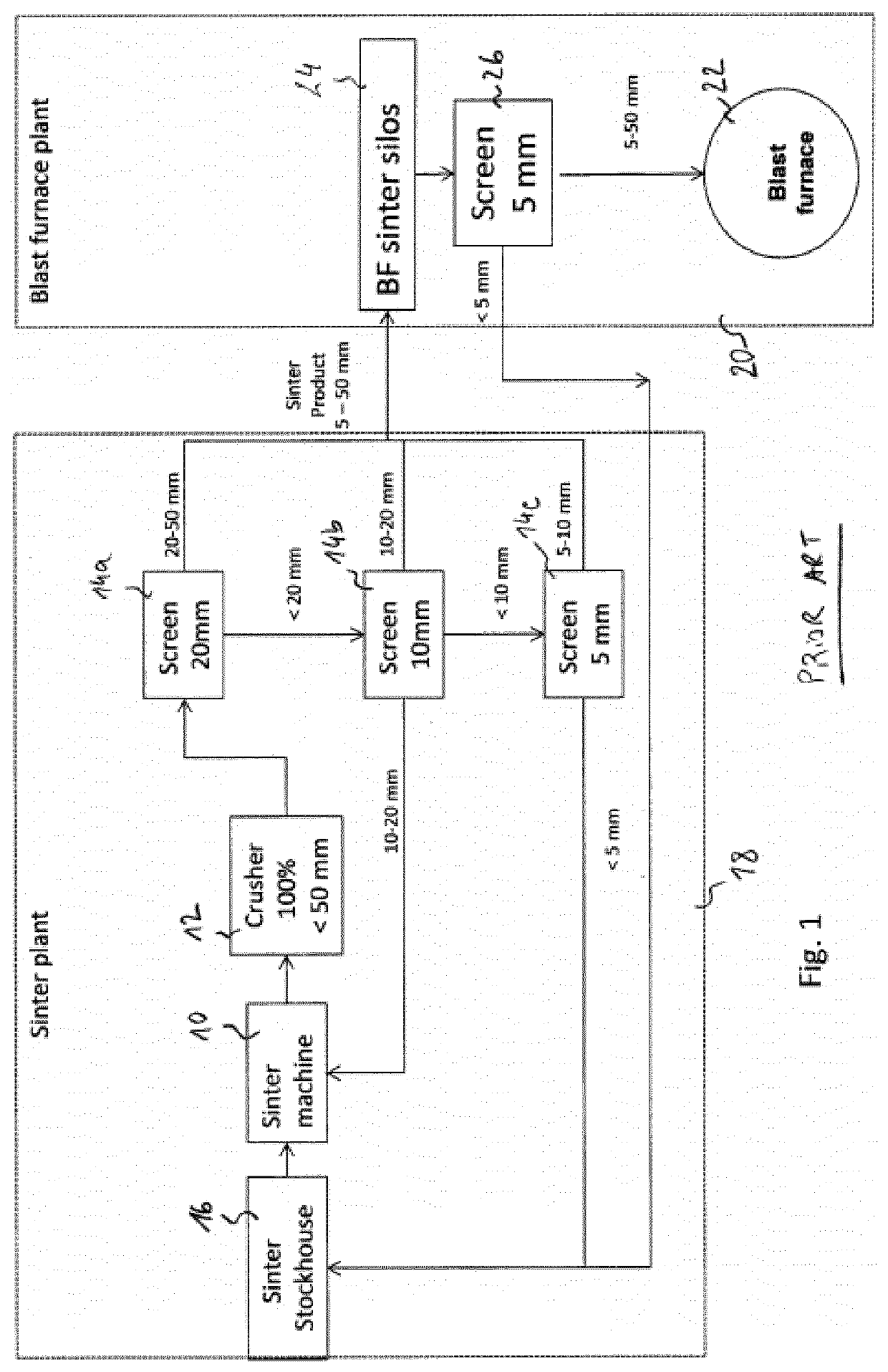
[0033]As explained in the background section and summarized in FIG. 1, different sinter size fractions are produced in the conventional sinter plant operation before being mixed again in order to form the final sinter product with a broad particle size distribution.

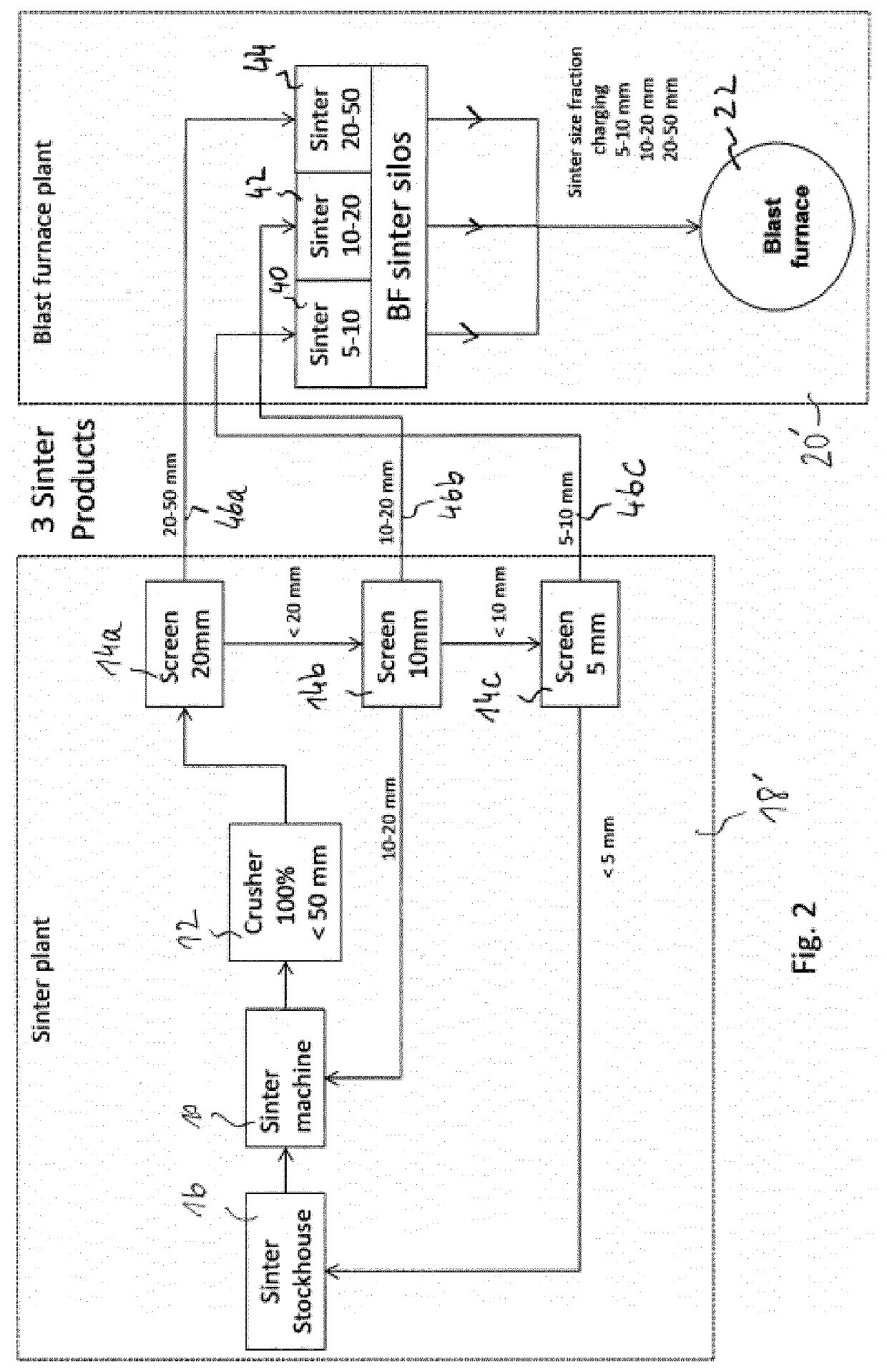
[0034]The present disclosure takes advantage of these different sinter size fractions produced in the conventional sinter plant operation and use them as such in the blast furnace instead of using them in a single product mix. As a result a more flexible blast furnace operation and especially a reduced pressure loss in the blast furnace shaft can be achieved.

[0035]An embodiment of the present method will now be described with reference to FIG. 2, where same or similar elements are designated by same reference signs. Sinter plant 18′ comprises a sinter stock house 16, a sinter mix preparation section (not shown) to prepare raw sinter nodules or granulates to be fired in the sinter machine 10, as is known in the art and bri...


PUM

PropertyMeasurementUnit
Sizeaaaaaaaaaa
Sizeaaaaaaaaaa
Sizeaaaaaaaaaa

Abstract

The invention concerns a method of operating a sinter plant, where a sinter mix is fired in a sintering machine, the method including
  • crushing fired sinter to below an upper particle size limit;
  • screening the crushed sinter to remove fines and separate at least two sinter size fractions, typically smaller, intermediate and upper size fractions;
  • storing each of the at least two sinter size fractions in a respective, separate storage bin, where
the screened sinter fractions are not mixed again at the sinter plant but are forwarded to the blast furnace plant, where they are stored in respective, separate storage bins, and the screened sinter fractions can be intermediately stored in separate bins at the sinter plant, before being forwarded to the blast furnace.

Description

TECHNICAL FIELD[0001]The present disclosure generally relates to the field of sinter production for the ironmaking industry. More specifically, the present disclosure relates to a method of operating a sinter plant.BACKGROUND[0002]As it is well known in ferrous metallurgy, the agglomeration of fine ferrous compounds, like fine ores, blast furnace dust (flue dust), steel works waste, mil scale etc., with finely grained fuel (e.g. coke fines) is referred to as the sintering process.[0003]In the sinter plant, the above-mentioned raw materials are stored in bins and a mixture of these feed materials (in predetermined amounts) is subject to a water addition within a so-called mixing and nodularizing drum, in order to produce small rice size nodules or granulates. The obtained raw sinter granulates are transferred to a traveling-grate type sintering furnace. Near the head or feed end of the grate, the bed is ignited on the surface by gas burners, and, as the mixture moves along on the tra...

Claims


Application Information

Patent Timeline
IPC IPC(8): C22B1/20F27B21/00
CPCC22B1/20F27B21/00C21B5/00C21B5/008
Inventor KINZEL, KLAUS PETER
Owner PAUL WURTH SA
Why Eureka
Try Eureka