Refrigerant compressor

a refrigerant compressor and compressor technology, applied in the direction of positive displacement liquid engines, liquid fuel engine components, positive displacement pump components, etc., can solve the problems of undesirable motor cooling, internal heat of the compressor housing due to the compressed refrigerant in the discharge muffler, etc., to improve the efficiency of the refrigerant compressor and reduce the absorption

Inactive Publication Date: 2020-04-02
SECOP AUSTRIA
View PDF0 Cites 1 Cited by
  • Summary
  • Abstract
  • Description
  • Claims
  • Application Information

AI Technical Summary

Benefits of technology

[0039]Since the at least one suction muffler is arranged inside of the compressor housing upstream of the cylinder/piston unit in the direction of flow, the functional surface must exhibit a low absorptivity. This is true because, otherwise, the refrigerant inside of the suction muffler will be heated as a result of the high temperatures that are present inside of the compressor housing—among other things due to the compressed refrigerant discharged in the pressure tube. In this case, the functional surface is thus preferably embodied on the outer surface of the suction muffler facing the interior of the compres

Problems solved by technology

A heating of the interior of the compressor housing due to the compressed refri

Method used


Image

  • Refrigerant compressor
  • Refrigerant compressor

Examples


Embodiment Construction

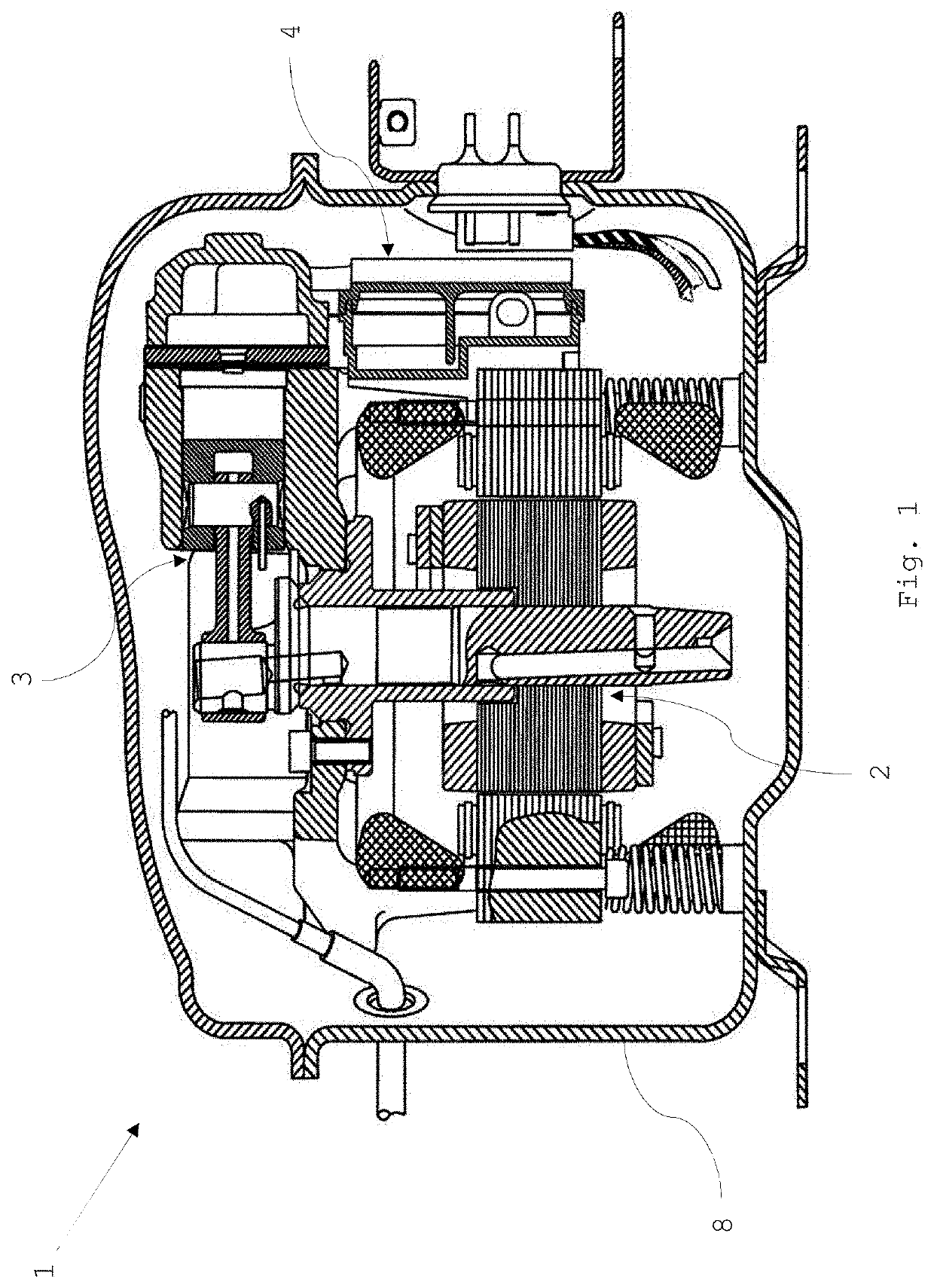
[0048]FIG. 1 shows a sectional view of a known refrigerant compressor 1. The refrigerant compressor 1 comprises a compressor housing 8, a drive unit 2, a piston / cylinder unit 3 in which the cyclical compression of a refrigerant takes place, and at least one sound-damping unit 4.

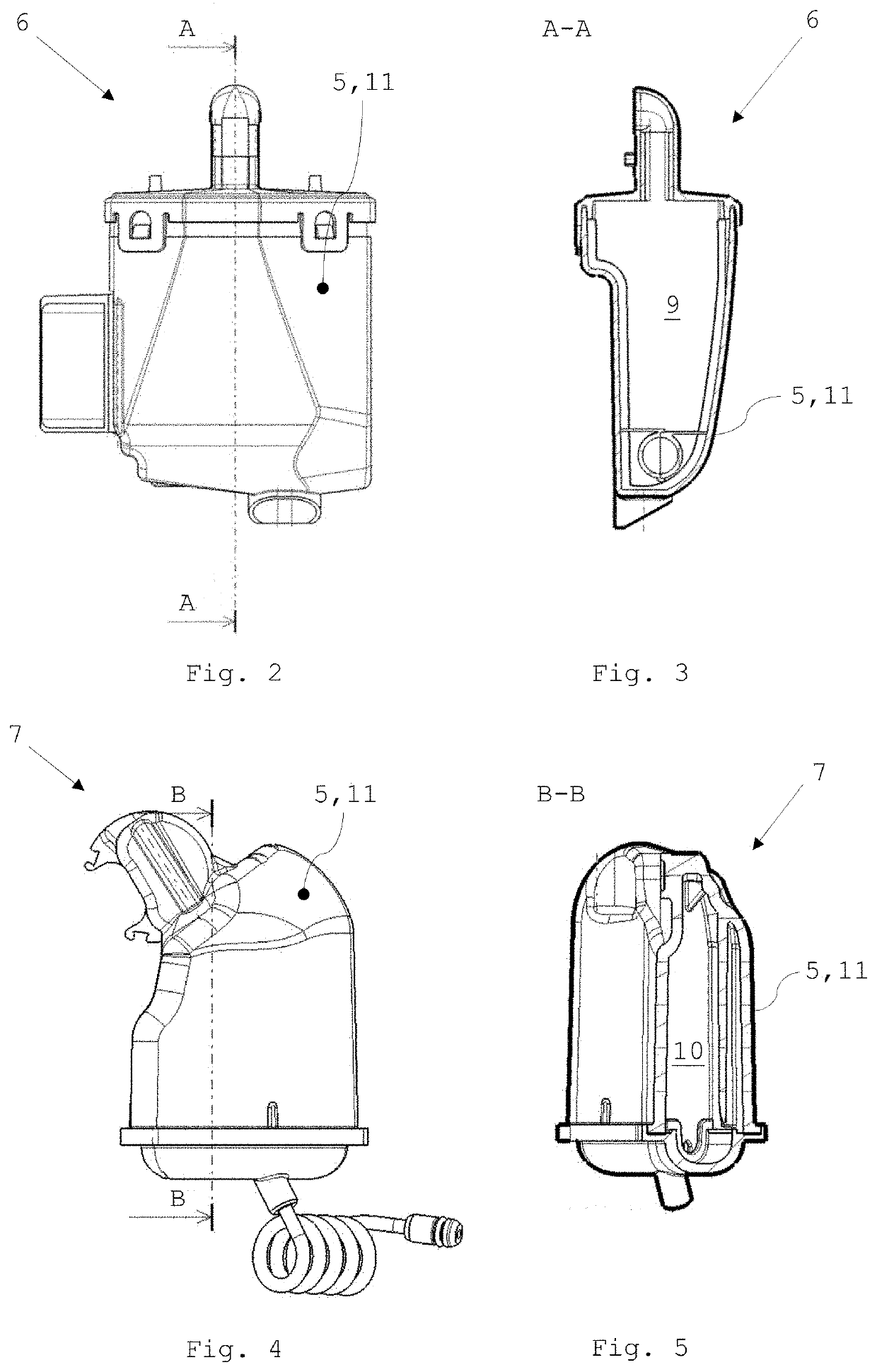
[0049]The at least one sound-damping unit 4 can be a suction muffler 6 and / or a discharge muffler 7. The suction muffler 6 is arranged upstream of the piston / cylinder unit 3 in the direction of flow of the refrigerant, whereas the discharge muffler 7 is located downstream of the piston / cylinder unit 3 in the direction of flow of the refrigerant.

[0050]On the path between the entry of the refrigerant into the compressor housing 8 and the intake valve of the piston / cylinder unit 3, there occurs, as mentioned previously, an undesired heating of the refrigerant. This can be attributed to the heating of the interior of the compressor housing 8, which occurs, among other things, as a result of the compressed refrige...


PUM


Abstract

Refrigerant compressor includes an electrical drive unit, a piston/cylinder unit which can be driven by the drive unit for the cyclical compression of refrigerant, and at least one sound-damping unit made of a thermoplastic, through which sound-damping unit refrigerant can flow and which sound-damping unit includes at least one damping chamber. The at least one sound-damping unit is connected to the piston/cylinder unit in order to enable an exchange of refrigerant between the sound-damping unit and piston/cylinder unit. The at least one sound-damping unit includes at least in sections a functional surface. The functional surface is embodied such that an emissivity of a section of the sound-damping unit includes the functional surface is less than 0.7. The at least one sound-damping unit or at least one of the sound-damping units is embodied as a discharge muffler arranged downstream of the piston/cylinder unit in the direction of flow.

Description

CROSS-REFERENCE TO RELATED APPLICATION[0001]This application claims priority under 35 U.S.C. § 119(a) to Europe Application No. 18 198 034.3 filed Oct. 1, 2018, the disclosure of which is expressly incorporated by reference herein in its entirety.FIELD OF THE INVENTION[0002]The present invention relates to a refrigerant compressor comprising an electrical drive unit, a piston / cylinder unit which can be driven by the drive unit for the cyclical compression of refrigerant, and at least one sound-damping unit made of a thermoplastic, through which sound-damping unit refrigerant can flow and which sound-damping unit comprises at least one damping chamber, wherein the at least one sound-damping unit is connected to the piston / cylinder unit in order to enable an exchange of refrigerant between the sound-damping unit and piston / cylinder unit.DISCUSSION OF BACKGROUND INFORMATION[0003]Hermetically encapsulated refrigerant compressors have been known for quite some time and are primarily used...

Claims


Application Information

Patent Timeline
IPC IPC(8): F04B39/00
CPCF04B39/122F04C29/068F04B39/123F04B39/0061F04B39/0005F04B39/0072F04B39/0083F04B39/06F05C2201/021F05C2201/0406F04B39/0027F04B39/0033F04B53/001
Inventor FREIBERGER, ALFRED
Owner SECOP AUSTRIA
Why Eureka
Try Eureka