
Method for FinFET Fabrication and Structure Thereof

a technology of finfet and fabrication method, which is applied in the direction of semiconductor devices, electrical apparatus, transistors, etc., can solve the problems of uneven etching of dielectric materials, flaws in subsequent formed features, and increased complexity of scaling down of ic processing and manufacturing,

Active Publication Date: 2020-04-02
TAIWAN SEMICON MFG CO LTD
View PDF0 Cites 11 Cited by
  • Summary
  • Abstract
  • Description
  • Claims
  • Application Information

AI Technical Summary

Benefits of technology

The present patent provides methods to increase the uniformity of fin performance in a semiconductor device. This is achieved by treating the surface of the semiconductor fin to achieve a consistent etch rate for the dielectric material on both sides of the fin. This results in a more uniform performance of the fins and can be easily integrated into existing manufacturing processes.

Problems solved by technology

Such scaling down has also increased the complexity of processing and manufacturing ICs.
Such seams may cause various issues during subsequent processes, resulting in flaws in subsequent formed features.
For example, a seam may appear asymmetrically on one side of a fin but not on the other side, which causes uneven etching of the dielectric material surrounding the fin in a dielectric material recess process.
This affects the performance uniformity of the FinFET devices.
Thus, the existing techniques have not proved entirely satisfactory in all aspects.

Method used


Image

  • Method for FinFET Fabrication and Structure Thereof
  • Method for FinFET Fabrication and Structure Thereof
  • Method for FinFET Fabrication and Structure Thereof

Examples


Embodiment Construction

[0007]The following disclosure provides many different embodiments, or examples, for implementing different features of the provided subject matter. Specific examples of components and arrangements are described below to simplify the present disclosure. These are, of course, merely examples and are not intended to be limiting. For example, the formation of a first feature over or on a second feature in the description that follows may include embodiments in which the first and second features are formed in direct contact, and may also include embodiments in which additional features may be formed between the first and second features, such that the first and second features may not be in direct contact. In addition, the present disclosure may repeat reference numerals and / or letters in the various examples. This repetition is for the purpose of simplicity and clarity and does not in itself dictate a relationship between the various embodiments and / or configurations discussed.

[0008]F...


PUM


Abstract

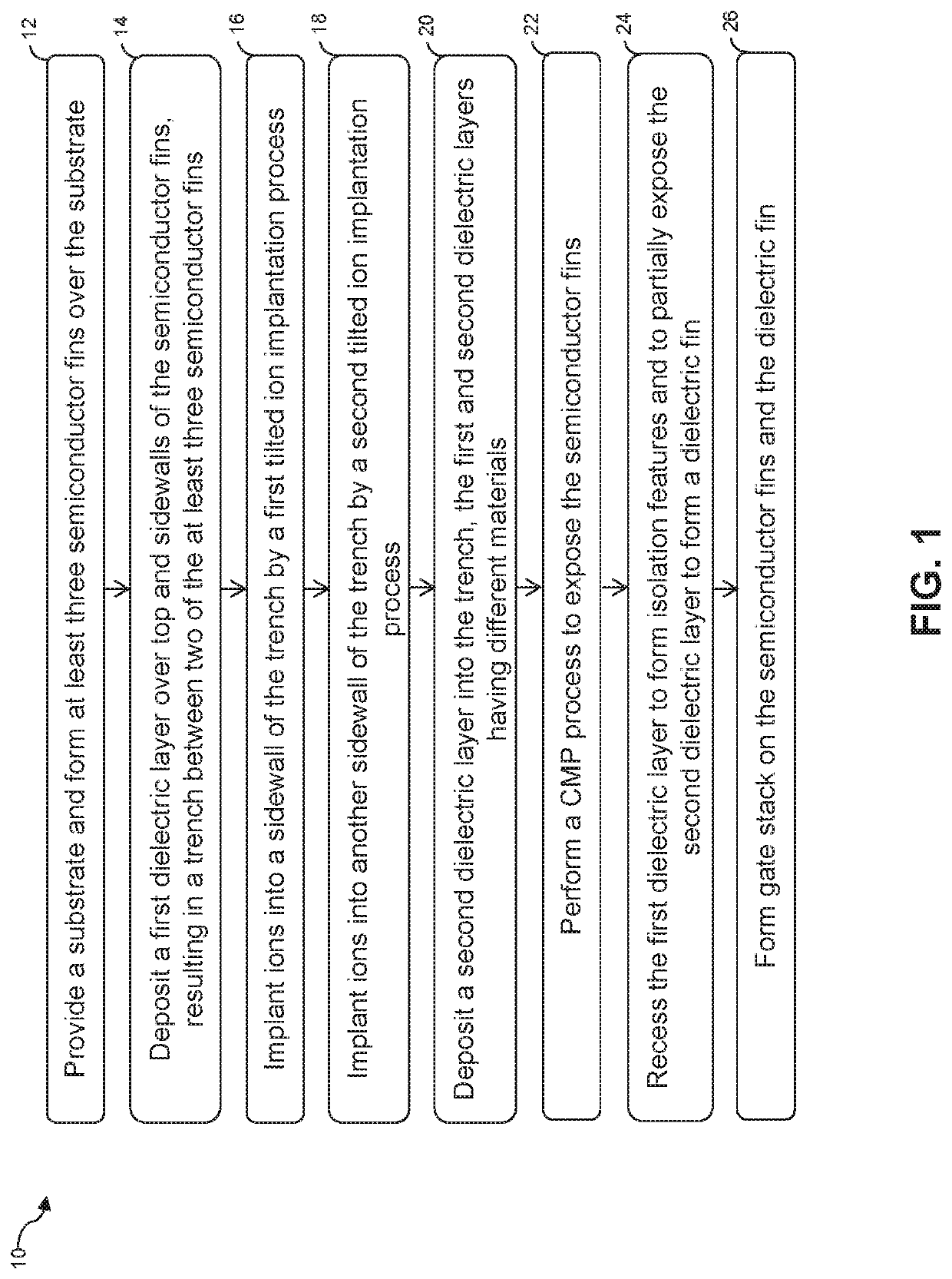
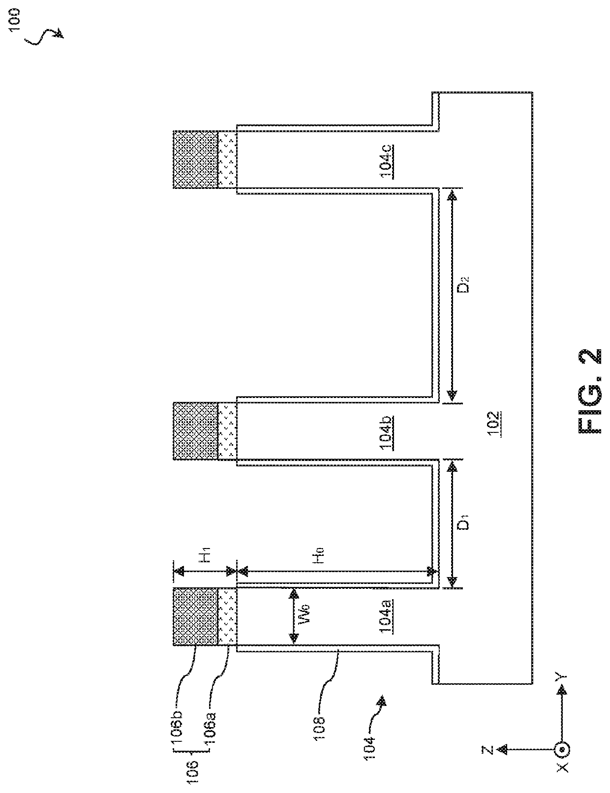
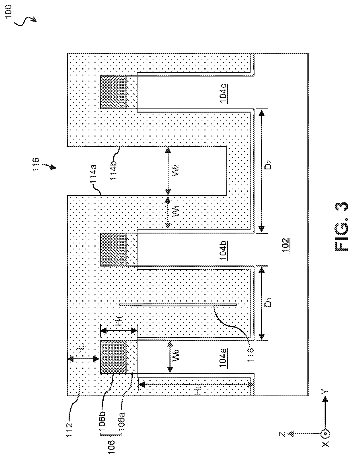
A method for FinFET fabrication includes forming at least three semiconductor fins over a substrate, wherein first, second, and third of the semiconductor fins are lengthwise substantially parallel to each other, spacing between the first and second semiconductor fins is smaller than spacing between the second and third semiconductor fins; depositing a first dielectric layer over top and sidewalls of the semiconductor fins, resulting in a trench between the second and third semiconductor fins, bottom and two opposing sidewalls of the trench being the first dielectric layer; implanting ions into one of the two opposing sidewalls of the trench by a first tilted ion implantation process; implanting ions into another one of the two opposing sidewalls of the trench by a second tilted ion implantation process; depositing a second dielectric layer into the trench, the first and second dielectric layers having different materials; and etching the first dielectric layer.

Description

PRIORITY DATA[0001]This application claims priority to U.S. Provisional Patent Application Ser. No. 62 / 737,798 filed on Sep. 27, 2018, the entire disclosure of which is hereby incorporated herein by reference.BACKGROUND[0002]The semiconductor integrated circuit (IC) industry has experienced exponential growth. Technological advances in IC materials and design have produced generations of ICs where each generation has smaller and more complex circuits than the previous generation. In the course of IC evolution, functional density (i.e., the number of interconnected devices per chip area) has generally increased while geometry size (i.e., the smallest component (or line) that can be created using a fabrication process) has decreased. This scaling down process generally provides benefits by increasing production efficiency and lowering associated costs. Such scaling down has also increased the complexity of processing and manufacturing ICs.[0003]In the formation of FinFET devices, tren...

Claims


Application Information

Patent Timeline
IPC IPC(8): H01L21/8234H01L27/088H01L21/265H01L21/02H01L21/3105H01L21/311H01L21/764
CPCH01L27/0886H01L21/31053H01L21/02164H01L21/31116H01L21/823431H01L21/26586H01L21/764H01L21/0228H01L21/823481H01L29/66795H01L29/1033H01L21/76237H01L21/76224H01L29/6681H01L21/31155H01L21/76229
Inventor LIN, HAN-YUJHAN, YI-RUEILEE, FANG-WEILIN, TZE-CHUNGHUANG, CHAO-HSIENLIN, LI-TELIN, PINYENMINEJI, AKIRA
Owner TAIWAN SEMICON MFG CO LTD
Learn More