Automatic Precision Worktop for Drilling without Deviation for Cylindrical Workpiece

Inactive Publication Date: 2020-04-09
WAN HING CHEUNG
View PDF3 Cites 18 Cited by
  • Summary
  • Abstract
  • Description
  • Claims
  • Application Information

AI Technical Summary

Benefits of technology

[0016]The technical effect of the invention is to provide an automatic precision worktop for drilling without deviation for cylindrical workpiece. The driving motor drives rotation of the first connecting rod, which drives rotation of the second connecting rod. The second connecting rod drives the first slider to slide on the third sliding rail so that the toggle block is driven to move. One end of the U-shaped rod rotates to one side of the toggle block away from the push cylinder. The toggle block moves and engages with the toggle strip so that the loading plate intermittently moves towards the push cylinder along the first sliding rail with the same distance every time. When the axis of the through slots coincides with the output direction of the push cylinder, the push cylinder pushes the workpiece into the receiving groov

Problems solved by technology

With the increase of human resources costs, most enterprises consider the automatic drilling machine as the development direction.
Nowadays, the drilling machine directly drills the workpiece, but in some special cases

Method used


Image

  • Automatic Precision Worktop for Drilling without Deviation for Cylindrical Workpiece
  • Automatic Precision Worktop for Drilling without Deviation for Cylindrical Workpiece
  • Automatic Precision Worktop for Drilling without Deviation for Cylindrical Workpiece

Examples


Embodiment Construction

[0030]The invention is illustrated in accordance with figures. The figures as simplified diagrams demonstrate the basic structures of the apparatus of embodiments of the invention. Thus; the invention is not limited to the figures.

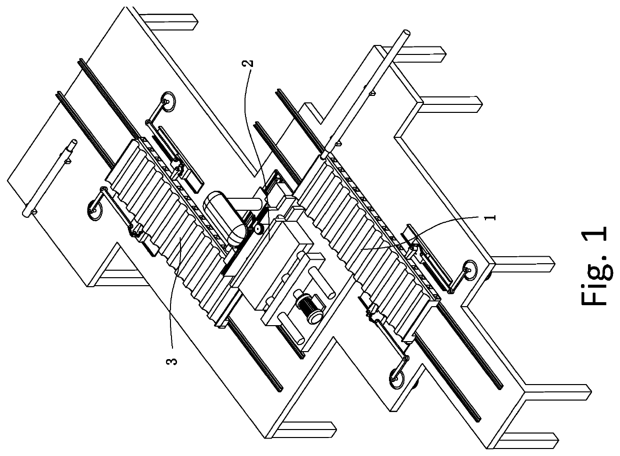
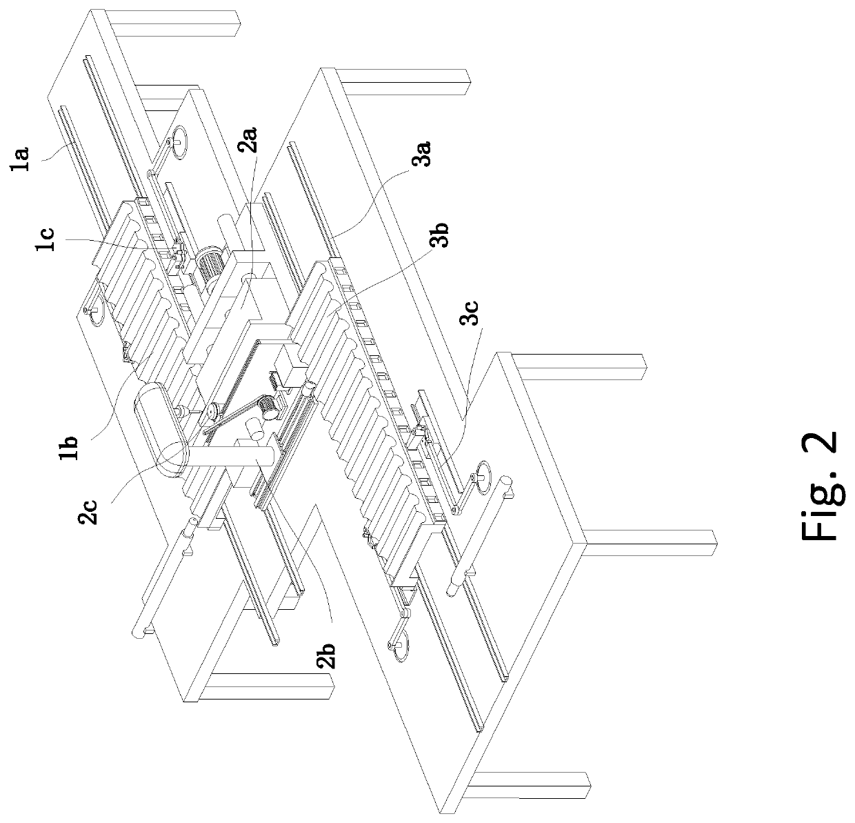
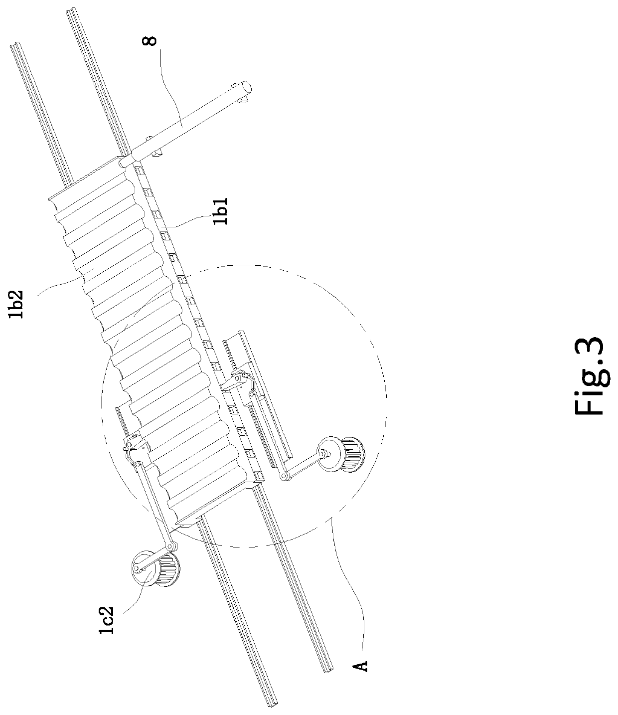
[0031]Referring to FIGS. 1-10, an automatic precision worktop for drilling without deviation for cylindrical workpiece includes a loading device 1, a drilling device 2 and an uploading device 3. The loading device 1 and the uploading device 3 are respectively disposed on two sides of the drilling device 2. The loading device 1 includes a first sliding rail 1a disposed horizontally on the side of the drilling device 2, a loading plate 1 disposed on the first sliding rail 1a and slidingly engaged with the first sliding rail 1a, and two first linkages 1c driving the loading plate 1b to slide on the first sliding rail 1a. Each linkage 1c includes a link mechanism, and a driving motor 1c2 that drives movement of the link mechanism. Two sides of the loading plat...


PUM

PropertyMeasurementUnit
Timeaaaaaaaaaa

Abstract

The invention relates to an automatic precision worktop for drilling without deviation for cylindrical workpiece which includes a loading device, a drilling device and an uploading device. The loading device includes a first sliding rail disposed horizontally on the side of the drilling device, a loading plate disposed on the first sliding rail and slidingly engaged with the first sliding rail, and two first linkages driving the loading plate to slide on the first sliding rail. Each linkage includes a link mechanism, and a driving motor that drives movement of the link mechanism. Two sides of the loading plate are respectively provided with a third sliding rail slidably engaged with two link mechanisms. The drilling device includes a clamping device, a drilling mechanism located on the side of the clamping device and a positioning mechanism slidingly engaged with the clamping device. The uploading mechanism includes a second sliding rail parallel to the first sliding rail, an uploading plate located on the second sliding rail and engaging the second sliding rail, and two second linkages that drive the uploading plate to slide on the second sliding rail. The present invention avoids large deviation of the drill bit, which reduces the defective rate of the workpiece, and avoid unnecessary waste of cost.

Description

FIELD OF THE INVENTION[0001]The invention relates to the field of precision workpiece processing equipment, in particular to an automatic precision worktop for drilling without deviation for cylindrical workpiece.BACKGROUND[0002]A drill is a machine and equipment that uses a tool that is harder and sharper than the target to leave a cylindrical hole in the target by means of rotary cutting or rotary extrusion. In order to achieve the desired results, the precision component is drilled. The drilling machine has a semi-automatic drilling machine and a fully automatic drilling machine. With the increase of human resources costs, most enterprises consider the automatic drilling machine as the development direction.[0003]Nowadays, the drilling machine directly drills the workpiece, but in some special cases, for example, the direct drilling on the cylindrical side of the cylindrical workpiece will slide off, causing a large error and increasing the defective rate of the workpiece and thu...

Claims


Application Information

Patent Timeline
IPC IPC(8): B23Q3/06B23B41/12B23Q7/06B23Q7/08
CPCB23Q2703/10B23B41/12B23Q7/06B23Q7/08B23Q3/062B23Q3/06B23Q7/00B23B41/003B23B47/281B23B2215/72B23Q7/001B23Q7/1489
Inventor WAN, HING CHEUNG
Owner WAN HING CHEUNG
Why Eureka
Try Eureka