
Electrical leakage determination system

Active Publication Date: 2020-04-16
DENSO CORP
View PDF0 Cites 3 Cited by
  • Summary
  • Abstract
  • Description
  • Claims
  • Application Information

AI Technical Summary

Benefits of technology

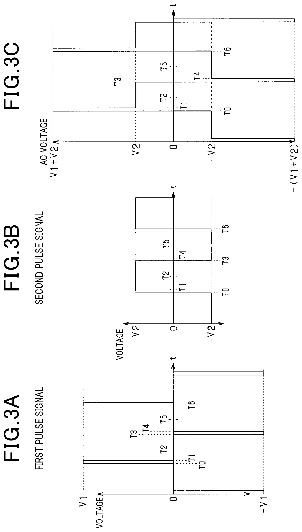
The present patent aims to improve the accuracy of voltage detection by reducing the influence of ground capacitance. It does this by outputting a greater absolute value of the AC voltage during the preparation period before the detection timing, which allows the ground capacitance to charge within a short period. This helps to suppress or reduce errors caused by ground capacitance and improve determination accuracy. Additionally, it allows for a faster detection timing and a shorter determination period.

Problems solved by technology

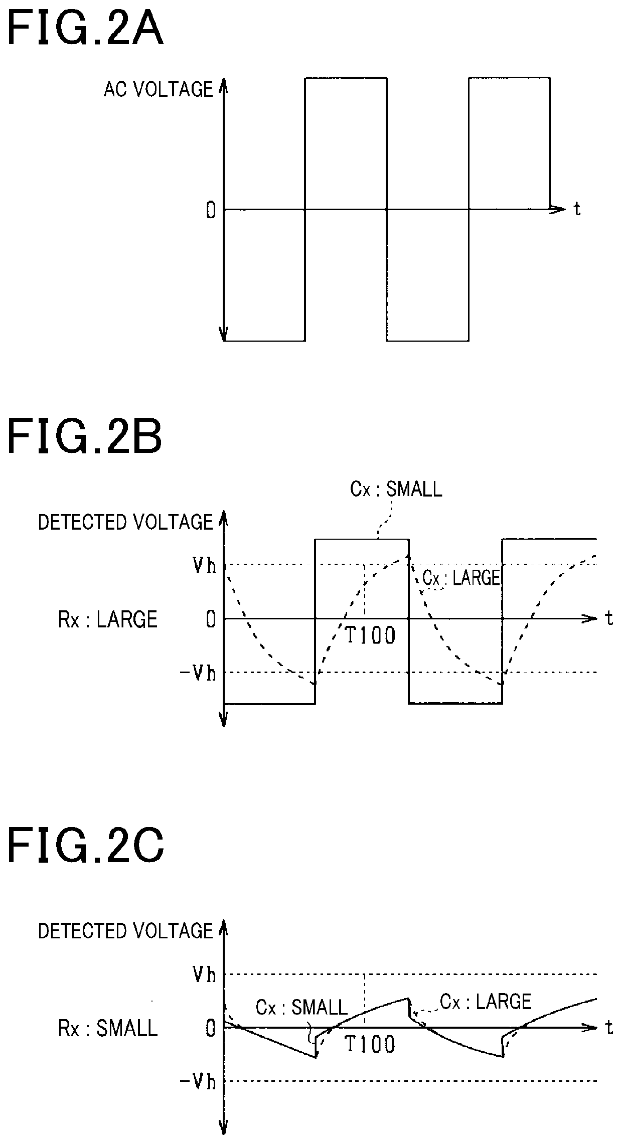
In general, when the ground capacitance increases, a rectangular wave slowly rises (a CR time constant becomes greater), thereby increasing a detection error while decreasing detection accuracy.
However, in such a situation, since it takes a longer time to detect the voltage, determination needs a longer period as a problem.

Method used


Image

  • Electrical leakage determination system
  • Electrical leakage determination system
  • Electrical leakage determination system

Examples


first embodiment

[0033]Referring now to the drawings, wherein like reference numerals designate identical or corresponding parts throughout the several views thereof, and to FIG. 1, the present disclosure is described.

[0034]The first embodiment of the present disclosure is applied to a vehicle (for example, a hybrid car and an electric motor car) including an electric rotary motor acting as a primary in-vehicle machine with an electrical leakage determination system.

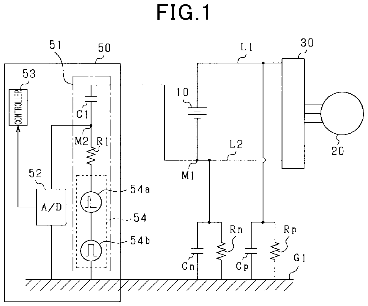
[0035]As illustrated in FIG. 1, an in-vehicle motor control system is provided in this embodiment and includes an assembled battery 10, a motor 20 and an inverter 30. The in-vehicle motor control system also includes an electrical leakage determination system 50.

[0036]The assembled battery 10 is electrically connected to the motor 20 via the inverter 30. The assembled battery 10 is, for example, a secondary battery having more than 100V across terminals and is configured by connecting multiple battery modules in series with each other. E...

second embodiment

[0085]Now, an electrical leakage determination system 50 according to the present disclosure is herein below described with reference to FIGS. 5 to 7.

[0086]As described earlier, the oscillator 54 of the first embodiment includes the first AC power supply 54a which outputs the first pulse signal and the second AC power supply 54b which outputs the second pulse signal. Now, such a configuration is modified in the second embodiment.

[0087]Specifically, as illustrated in FIG. 5, as an oscillator 54, an AC power supply enabled to arbitrarily change a waveform of an AC voltage is employed. Specifically, as illustrated in FIG. 6, the waveform output by the oscillator 54 is a saw wave in which an absolute voltage value comes to peaks at respective time points (time points T20 and T23) at which preparation periods start. After the respective time points T20 and T23 in the saw wave, the absolute voltage value gradually decreases.

[0088]Hence, by employing such a waveform as an AC voltage, the g...

third embodiment

[0090]Now, an electrical leakage determination system 50 according to the present disclosure is herein below described with reference to FIGS. 8 to 15.

[0091]In the above-described first and second embodiments, by increasing the absolute value of the AC voltage during the preparation period and thereby allowing the ground capacitance Cx to charge, a voltage corresponding to the ground fault resistance Rx is detected at the detection timing. However, when the absolute value of the AC voltage output during the preparation period is too low and is insufficient for the ground capacitance Cx to charge during the preparation period, as similar to the related art of FIG. 4A, the ground capacitance Cx can continuously charge even after the end of the preparation period. As a result, a voltage detected at the connection point (M2) is likely to decrease due to influence of the continuous charging resulting in erroneously determination that an electrical leakage occurs.

[0092]By contrast, when t...


PUM


Abstract

An electrical leakage determination system determines if an electrical leakage occurs between each of power supply paths and a grounding section. The electrical leakage determination system includes a coupling capacitor with one end connected to an anode-side power supply path, a resistor connected to the other end of the coupling capacitor, and an oscillator connected to the resistor to output an AC voltage to the resistor. A determiner detects a voltage at a connection point located between the coupling capacitor and the resistor when the oscillator outputs an AC voltage to the resistor. The determiner determines if the electrical leakage occurs based on the detected voltage. The oscillator increases an absolute value of an AC voltage output during a preparation period provided prior to a detection timing when a voltage is detected at a connection point greater than an absolute value of an AC voltage output at the detection timing.

Description

CROSS-REFERENCE TO RELATED APPLICATIONS[0001]This application is based on and claims the benefit of priority from earlier Japanese Patent Application No. 2018-195395 filed on Oct. 16, 2018 and Japanese Patent Application No. 2019-083425 filed on Apr. 24, 2019, the descriptions of which are incorporated herein by reference.BACKGROUNDTechnical Field[0002]Embodiments of this disclosure relate to an electrical leakage determination system.Related Art[0003]As an electrical leakage determination system (i.e., a ground fault detection system for a vehicle) that determines if an electrical leakage occurs (i.e., not an insulation state) in an electric system mounted on a vehicle based on a decrease in ground fault resistance is known. For example, it is discussed in JP-2003-250201-A that a rectangular wave is output to a signal line connected to the electric system and it is determined if an electrical leakage occurs based on a voltage value (a crest value) of the rectangular wave in the sig...

Claims


Application Information

Patent Timeline
IPC IPC(8): G01R31/02G01R31/42
CPCG01R31/42G01R31/50G01R31/52G01R31/40
Inventor WAKIMOTO, TORUSHINDO, YUSUKEKOUDA, MASAKAZU
Owner DENSO CORP
Learn More