Vehicle lamp and lighting circuit
a technology of lighting circuit and vehicle lamp, which is applied in the direction of electroluminescent light sources, transportation and packaging, lighting and heating apparatus, etc., can solve the problems of high cost, generation of electromagnetic noise, and high efficiency, and achieve the effect of reducing electromagnetic noise and easy to cope with electromagnetic nois
- Summary
- Abstract
- Description
- Claims
- Application Information
AI Technical Summary
Benefits of technology
Problems solved by technology
Method used
Image
Examples
first embodiment
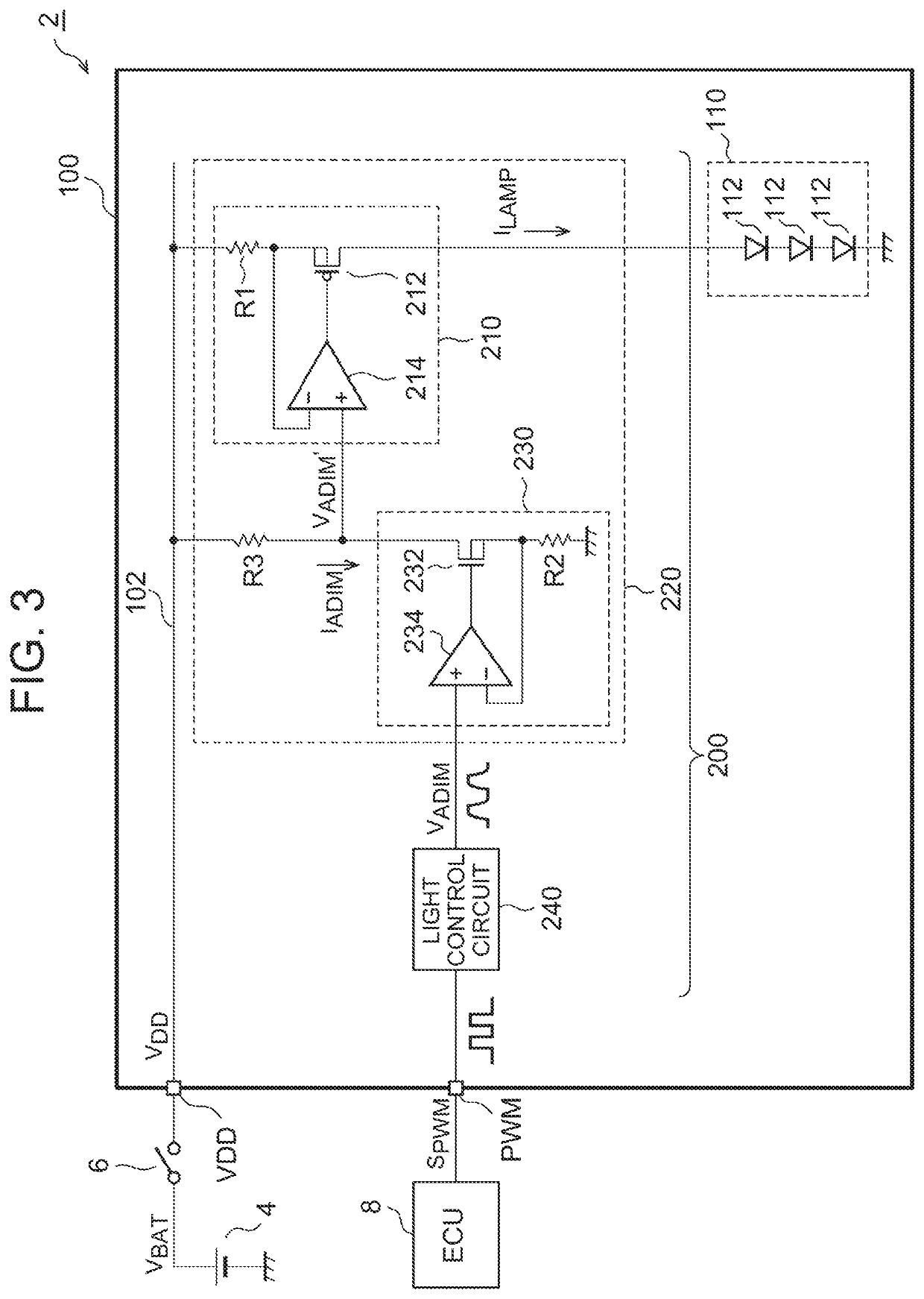
[0059]FIG. 3 is a block diagram of a lamp system 2 including a lamp 100 according to a first embodiment. The lamp system 2 includes a battery 4, a switch 6, and an electronic control unit (ECU) 8. The lamp 100 has an electric power source terminal VDD that receives supply of an electric power source voltage VDD from the battery 4 through the switch 6. The switch 6 is controlled in accordance with turning on-off instructions for the lamp 100.
[0060]The lamp 100 includes a light source 110 and a lighting circuit 200. The light source 110 includes a plurality of light-emitting elements 112 connected in series. Although LEDs are suitable as the light-emitting elements 112, other semiconductor light-emitting elements, such as laser diodes (LDs) and organic EL elements may also be used.
[0061]The lighting circuit 200 supplies a driving current (lamp current) ILAMP to the light source 110, and controls the lamp current ILAMP to regulate the luminance of the light source 110.
[0062]The lightin...
second embodiment
[0083]In the first embodiment, the pulse signal SPWM is generated by the ECU 8. However, without being limited thereto, the pulse signal SPWM may be generated inside a lamp 100D. FIG. 8 is a block diagram of a lamp system 2D according to a second embodiment of the present disclosure. The lamp 100D has a control terminal CNT. The ECU 8 supplies to the control terminal CNT a control signal SCTRL that specifies a luminance or lighting mode of the light source 110. The control signal SCTRL may be an analog signal or may be a digital signal.
[0084]A lighting circuit 200D includes a pulse generator 260 in addition to the constant current circuit 220 and the light control circuit 240. The pulse generator 260 generates a pulse signal SPWM having a duty ratio corresponding to the control signal SCTRL. The light control circuit 240 softens the pulse signal SPWM generated by the pulse generator 260 to generate a light control signal VADIM.
[0085]The second embodiment makes it possible to reduce ...
third embodiment
[0092]FIG. 10 is a block diagram of a lamp system 2G including a lamp 100G according to a third embodiment. The lamp 100G includes two light sources 110_1, 110_2 that are different in function, and a lighting circuit 200G that controls turning on-off and luminance of the two light sources 110_1, 110_2.
[0093]The lamp 100G has a first input terminal IN1 that receives supply of a first input voltage VIN1 that becomes active (high level) during a period when the first light source 110_1 is to be turned on. The lamp 100G also has a second input terminal IN2 that receives supply of a second input voltage VIN2 that becomes active (high level) during a period when the light source 110_2 is to be turned on. In the present embodiment, the first input voltage VIN1 and the second input voltage VIN1 do not become active at the same time. For example, the lamp system 2G includes switches 6a, 6b. When the switch 6a is set to ON, the first input voltage VIN1 becomes active. When the switch 6b is se...
PUM
| Property | Measurement | Unit |
|---|---|---|
| voltage | aaaaa | aaaaa |
| resistance | aaaaa | aaaaa |
| current | aaaaa | aaaaa |
Abstract
Description
Claims
Application Information
 - R&D
- Intellectual Property
- Life Sciences
- Materials
- Tech Scout
- Unparalleled Data Quality
- Higher Quality Content
- 60% Fewer Hallucinations
Browse by: Latest US Patents, China's latest patents, Technical Efficacy Thesaurus, Application Domain, Technology Topic, Popular Technical Reports.
© 2025 PatSnap. All rights reserved.Legal|Privacy policy|Modern Slavery Act Transparency Statement|Sitemap|About US| Contact US: help@patsnap.com


