
Method and system for programming a cobot for a plurality of industrial cells

Active Publication Date: 2020-04-23
SIEMENS IND SOFTWARE GMBH
View PDF0 Cites 4 Cited by
  • Summary
  • Abstract
  • Description
  • Claims
  • Application Information

AI Technical Summary

Benefits of technology

The patent text describes methods, systems, and computer-readable media for programming a cobot for a plurality of cells in an industrial environment. A physical cobot is provided in a physical lab cell for training purposes. A virtual simulation system is provided for simulating the physical cobot in a virtual environment. A user interface is provided for user interaction with the virtual simulation system. The virtual cobot is connected to virtual lab objects and industrial objects in a virtual industrial cell to detect collisions and minimize collisions during teaching. A robotic program is generated based on the received inputs from the physical cobot's movement. The patent text focuses on facilitating the programming of cobots for industrial environments.

Problems solved by technology

However, in the lab there might be only a limited portion of all the physical obstacles present in each physical facility cell of the industrial facility, and the programmer needs to take into account all the possible obstacles for programming the cobot to avoid collisions during industrial operations in the industrial cell.
In the case of a facility including a plurality of industrial cells, the programmer's task becomes even more complex.
Current techniques for cobot programming in a multi-cell facility are cumbersome, tedious, error-prone, and otherwise ill-suited for the task.

Method used


Image

  • Method and system for programming a cobot for a plurality of industrial cells
  • Method and system for programming a cobot for a plurality of industrial cells
  • Method and system for programming a cobot for a plurality of industrial cells

Examples


Embodiment Construction

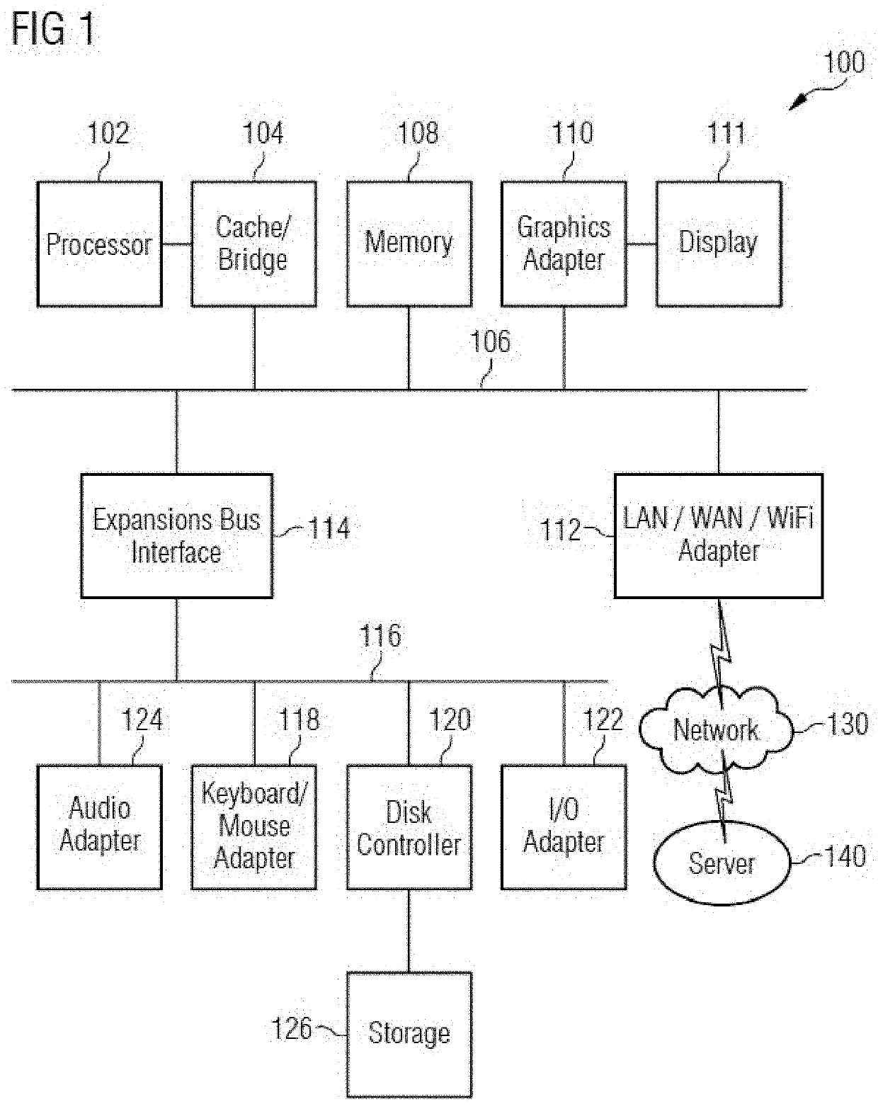
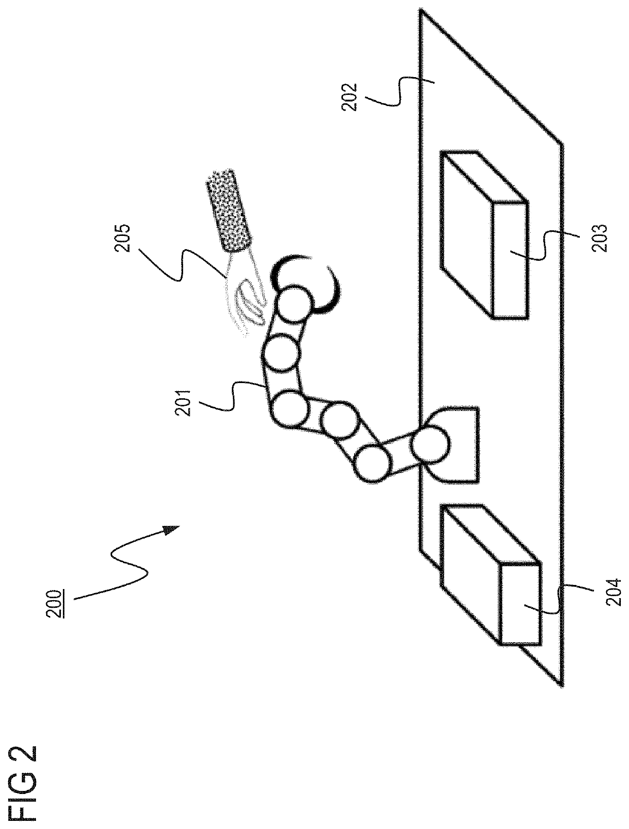
[0017]FIGS. 1 through 5, discussed below, and the various embodiments used to describe the principles of the present disclosure in this patent document are by way of illustration only and should not be construed in any way to limit the scope of the disclosure. Those skilled in the art will understand that the principles of the present disclosure may be implemented in any suitably arranged device. The numerous innovative teachings of the present application will be described with reference to exemplary non-limiting embodiments.

[0018]Previous techniques for cobot programming in a multi-cell facility require too much time and effort. The embodiments disclosed herein provide numerous technical benefits, including but not limited to the following examples.

[0019]Embodiments may enable programming cobots for industrial usage in tightly coupled physical-digital environments.

[0020]Embodiments may also enable cobot programmers to continue teaching the cobot in a manual manner.

[0021]Embodiment...


PUM


Abstract

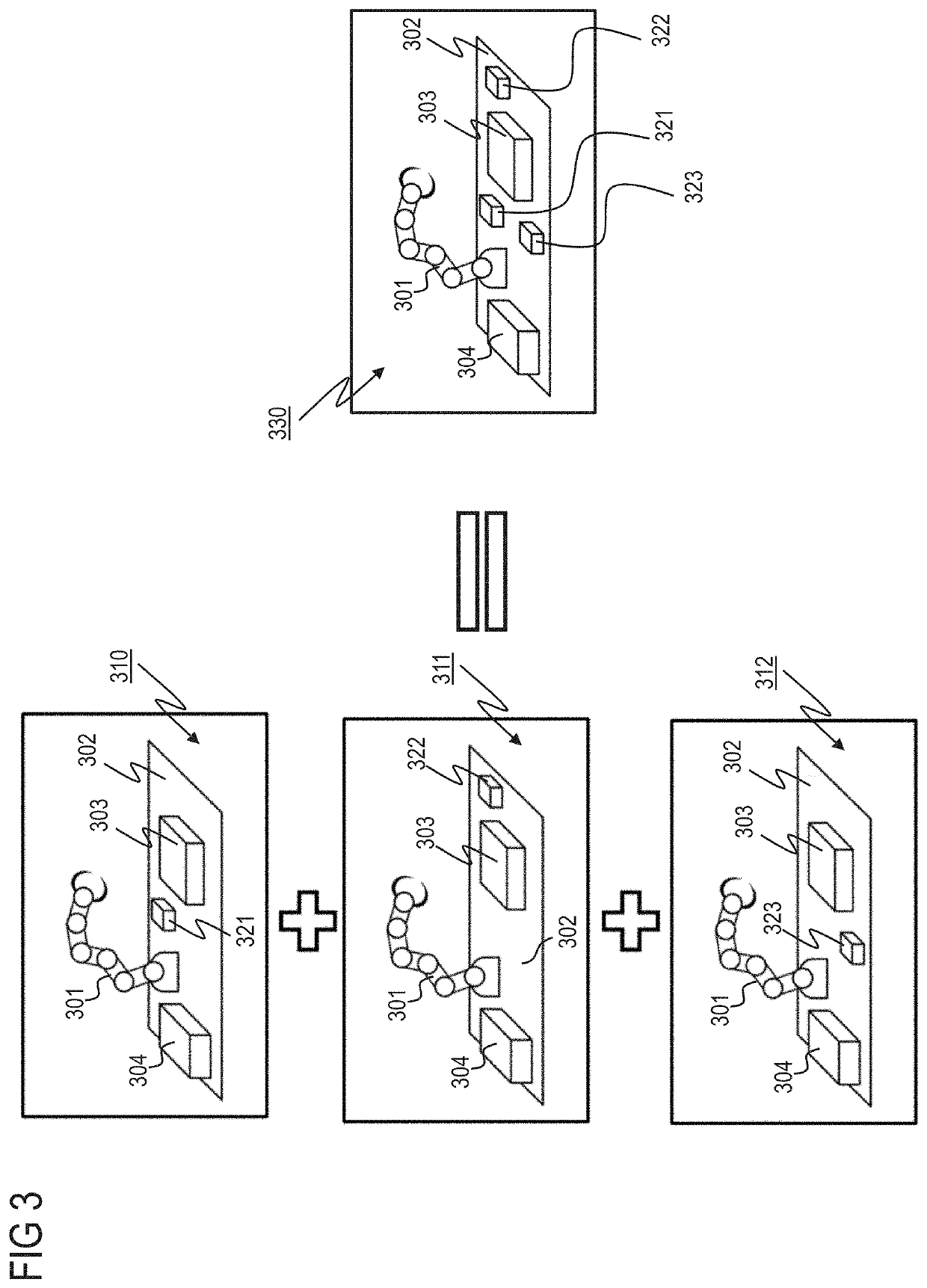
Systems and a method for programming for a plurality of cells of an industrial environment. A physical cobot is provided within a lab cell comprising lab physical objects. A virtual simulation system with a user interface is provided. The virtual simulation system receives information inputs on the virtual cobot, on the virtual lab cell comprising lab virtual objects, and on a plurality of virtual industrial cells comprising virtual industrial objects. The virtual cobot and the physical cobot are connected together. A superimposed meta-cell is generated by superimposing the plurality of virtual cells and the virtual lab cell so as to obtain a single superimposed meta cell including a set of superimposed virtual objects. The virtual cobot is positioned in the superimposed meta cell. Inputs are received from the physical cobot's movement during teaching whereby the physical cobot is moved in the lab cell to the desired position(s) while providing, via the user interface, a visualization of the virtual cobot's movement within the superimposed meta cell so that collisions with any object are minimized. A robotic program is generated based on the received inputs of the physical cobot's movement.

Description

TECHNICAL FIELD[0001]The present disclosure is directed, in general, to computer-aided design, visualization, and manufacturing (“CAD”) systems, product lifecycle management (“PLM”) systems, product data management (“PDM”) systems, and similar systems, that manage data for products and other items (collectively, “Product Data Management” systems or PDM systems). More specifically, the disclosure is directed to production environment simulation.BACKGROUND OF THE DISCLOSURE[0002]Traditional industrial robots are designed to operate autonomously or with limited human guidance. Cobots are robots intended to physically interact with humans in a shared workspace. The terms “cobots” and “co-robots” indicate “collaborative robots.” Cobots are being utilized in greater numbers in several industrial manufacturing fields.[0003]Cobots, being specifically conceived for human interactions, have the advantage of being safer than traditional robots, in that they are able to identify human proximity...

Claims


Application Information

Patent Timeline
IPC IPC(8): B25J9/16G05B19/4155B25J13/06
CPCB25J13/06B25J9/1666G05B2219/40476G05B19/4155B25J9/1671B25J9/1605G05B2219/40415G05B2219/31371G05B2219/31373G05B2219/39014G05B2219/40121G05B2219/40126G05B2219/40091G05B2219/40168G05B2219/40311G05B2219/40515G05B2219/39136G05B2219/40382Y02P90/80
Inventor HAZAN, MOSHEBADUSA, SHAUL
Owner SIEMENS IND SOFTWARE GMBH
Learn More