Pneumatic tire

a technology of pneumatic tires and treads, applied in the field of pneumatic tires, can solve the problems of affecting the balance of contact patch pressure and impairing the performance of dry road surfaces, and achieve the effect of improving water shedding performance and improving performan

Active Publication Date: 2020-04-23
TOYO TIRE & RUBBER CO LTD
View PDF0 Cites 2 Cited by
  • Summary
  • Abstract
  • Description
  • Claims
  • Application Information

AI Technical Summary

Benefits of technology

[0005]It is an object of the present disclosure to provide a pneumatic tire that will make it possible to simultaneously achieve...

Problems solved by technology

However, if contact patch pressure becomes too high toward the center of the lug, or contact patch pressure becomes too l...

Method used


Image

  • Pneumatic tire
  • Pneumatic tire
  • Pneumatic tire

Examples


first embodiment

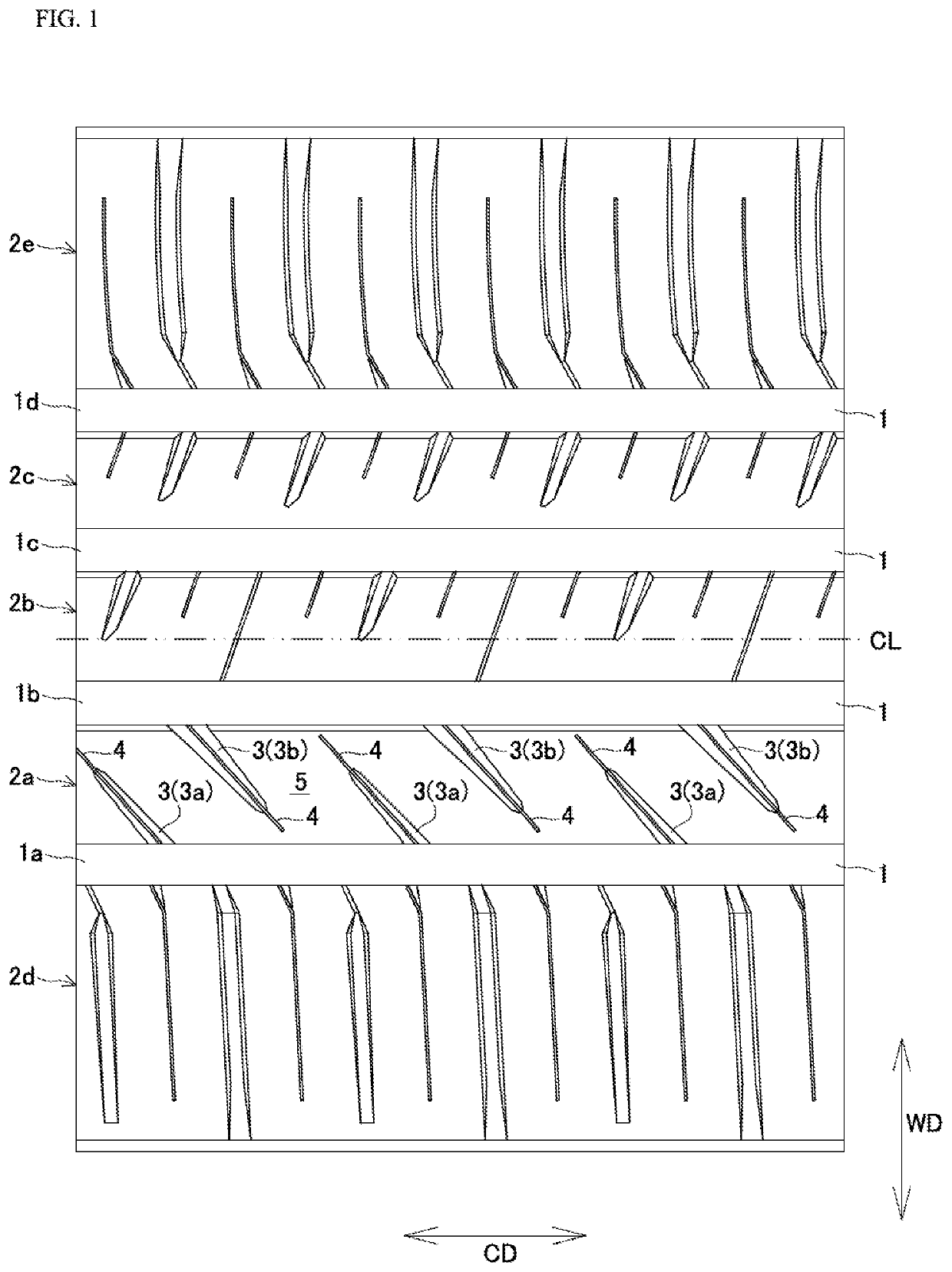
[0033]Below, a first embodiment in accordance with the present disclosure is described. In the drawings, “CD” refers to the tire circumferential direction, and “WD” refers to the tire width direction. The respective drawings show shapes as they would exist when the tire is still new.

[0034]While not shown in the drawings, a pneumatic tire in accordance with the first embodiment, in similar fashion as with an ordinary pneumatic tire, is provided with a pair of bead cores; a carcass that wraps around the bead cores in toroidal fashion; a belt layer arranged toward the exterior in the tire radial direction from a crown region of the carcass; and a tread region arranged toward the exterior in the tire radial direction from the belt layer.

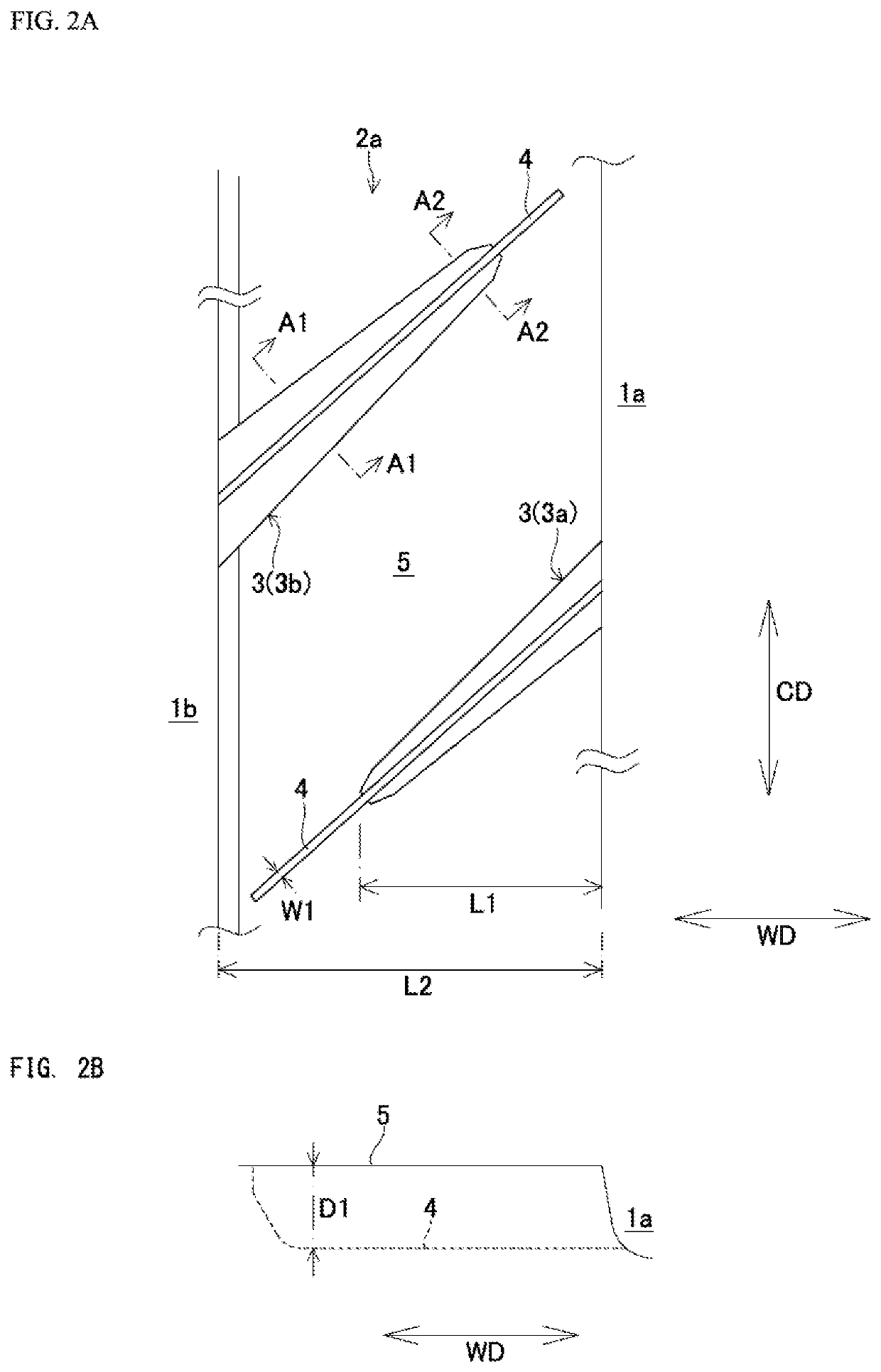
[0035]As shown in FIG. 1, the tread region has a plurality of major grooves 1 (1a, 1b, 1c, 1d) extending in the tire circumferential direction CD, and lug 2a that is partitioned by two major grooves 1a, 1b and that forms contact patch surface 5. The trea...

second embodiment

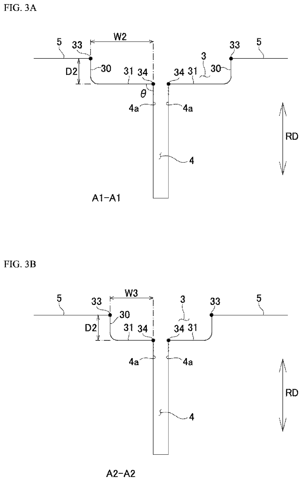
[0071]As shown in FIG. 8, FIG. 9, and FIG. 10A, the second embodiment is an embodiment in which sipe 4 of the first embodiment is not provided. FIG. 8 shows the situation that exists when first recessed regions 3a and second recessed regions 3b are arranged in alternating fashion in the tire circumferential direction CD at lug 2a. FIG. 9 is an enlarged view showing a first recessed region 3a and a second recessed region 3b. FIG. 10A is a sectional view taken along section A1-A1 in FIG. 9. As shown in FIG. 10A, planar base 31 extends in the horizontal direction. In accordance with a variation as shown in FIG. 10B, planar base 31 may be inclined in such fashion that the height thereof increases so as to be increasingly directed toward the exterior RD1 in the tire radial direction as one proceeds toward the center in the width direction of recessed region 3 as viewed in a section taken along the width direction of recessed region 3.

[0072]As described above, a pneumatic tire in accordan...


PUM


Abstract

A tire has a lug, a plurality of first recessed regions that extend from a first major groove, and a plurality of second recessed regions that extend from a second major groove. A central region of the lug protrudes relative to either end of the lug. The plurality of first and second recessed regions are arranged in alternating fashion along a tire circumferential direction. The respective recessed regions each has a planar base that extends in a width direction of the each recessed region. The planar base is horizontal, or is inclined in such fashion that a height thereof increases so as to extend further toward an exterior in a tire radial direction as one proceeds toward a center of the each recessed region. Width of the planar base increases as one proceeds from the center in the width direction of the lug to an end of the lug.

Description

BACKGROUND OF THE INVENTION[0001]The present disclosure relates to a pneumatic tire.[0002]Japanese Patent Application Publication Kokai No. 2017-65285 describes imparting a lug with a convexly curved shape so as to improve water shedding performance and so as to improve kinematic performance on a dry road surface.[0003]At Japanese Patent Application Publication Kokai No. 2017-65285, imparting the lug with a convexly curved shape causes contact patch pressure to be higher toward the center of the contact patch surface and to gradually decrease as one proceeds toward either end of the contact patch surface. It is described that this will allow adequate contact patch surface area to be attained at the lug, and will make it possible to improve kinematic performance on a dry road surface.[0004]However, if contact patch pressure becomes too high toward the center of the lug, or contact patch pressure becomes too low at the end of the lug, this will disturb the balance in contact patch pre...

Claims


Application Information

Patent Timeline
IPC IPC(8): B60C11/03B60C11/13B60C11/12
CPCB60C11/1353B60C11/1259B60C11/125B60C11/0304B60C2011/1361B60C2011/0369B60C2011/0365B60C11/1204B60C11/1236B60C11/1281B60C11/0302B60C11/0306B60C2011/0341B60C2011/0358B60C2011/0381B60C2011/0383B60C11/12B60C2011/0362B60C11/1392B60C11/1376
Inventor MIYAZAKI, TETSUJI
Owner TOYO TIRE & RUBBER CO LTD
Why Eureka
Try Eureka