Optical analysis device, optical analysis method, and optical analysis

Active Publication Date: 2020-04-23
HITACHI LTD
View PDF0 Cites 0 Cited by
  • Summary
  • Abstract
  • Description
  • Claims
  • Application Information

AI Technical Summary

Benefits of technology

The invention allows for faster analysis of a liquid sample by separating out its solution and scatterer components.

Problems solved by technology

As described above, a method of analyzing a solution component and a scatterer component in a liquid sample is known, but the solution component and the scatterer component in the liquid sample cannot be quickly analyzed by a single optical analysis device.

Method used


Image

  • Optical analysis device, optical analysis method, and optical analysis
  • Optical analysis device, optical analysis method, and optical analysis
  • Optical analysis device, optical analysis method, and optical analysis

Examples


first embodiment

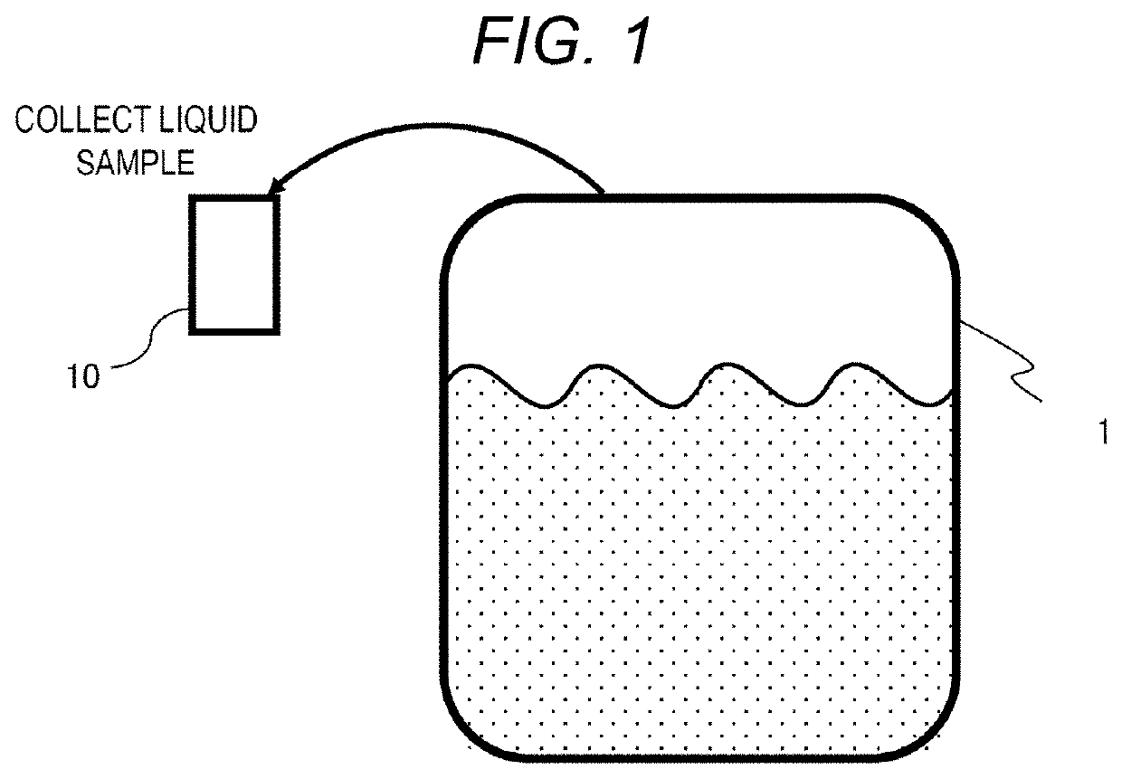
[0029]FIG. 1 is a diagram illustrating an outline of an optical analysis device 10 according to the invention.

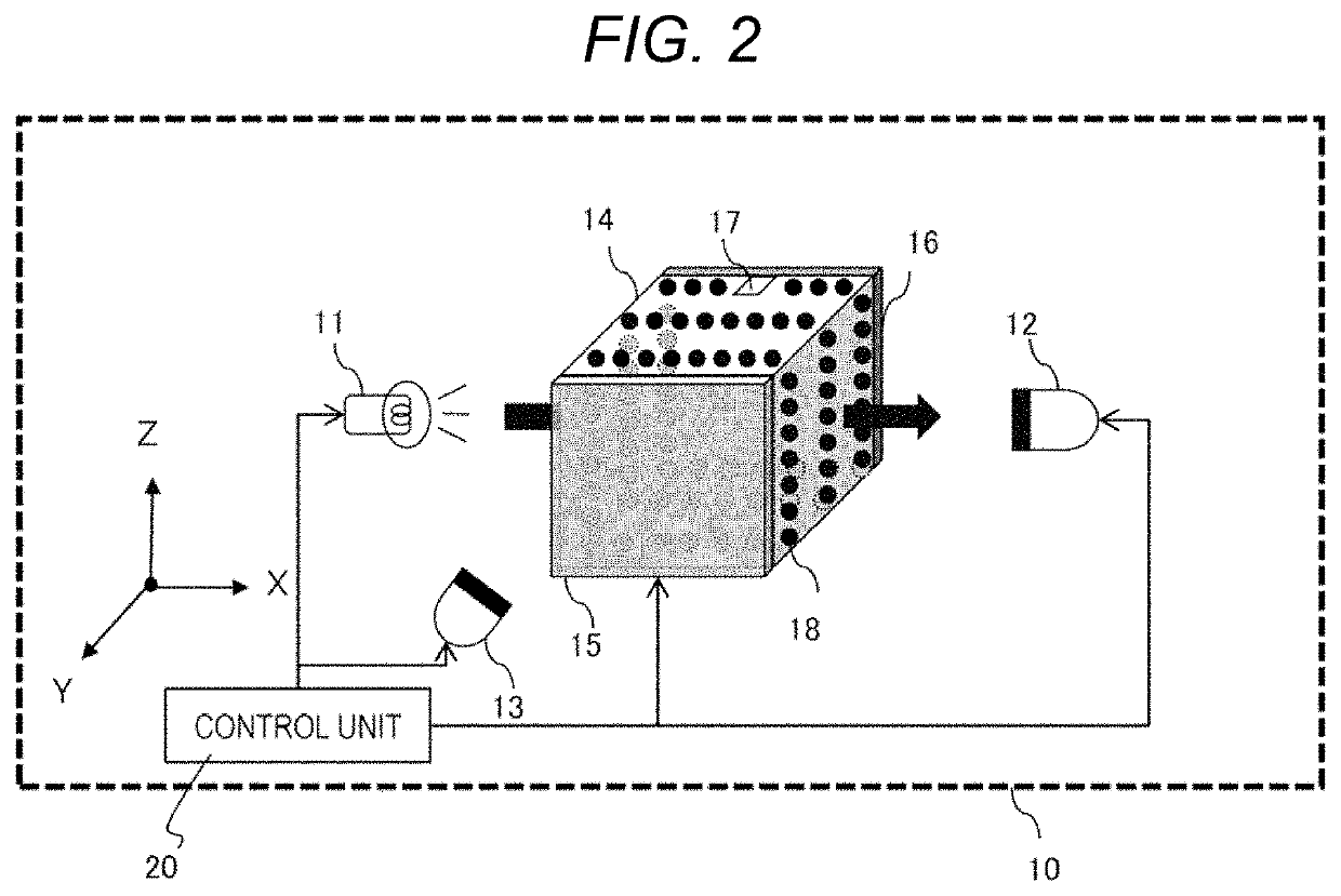
[0030]The optical analysis device 10 measures a solution component and a scatterer component in a liquid sample by setting the liquid sample collected from a reaction vessel 1 in which processing such as cell culture, chemical synthesis and the like is performed as an analysis target, irradiating the liquid sample accommodated in a measurement cell 14 (FIG. 2) with light of a predetermined wavelength, and performing optical analysis (for example, spectral analysis) of light that is transmitted through the liquid sample and light that is scattered by a scatterer in the liquid sample. The optical analysis is not limited to the spectral analysis, and other methods may be adopted.

[0031]The liquid sample is assumed to be, for example, a culture solution of cells, microorganisms and fungi, a liquid raw material for processing such as chemical synthesis, an emulsion containing an o...

second embodiment

[0070]FIG. 6 is a diagram illustrating an outline of an optical analysis system 30 according to the invention.

[0071]In the optical analysis system 30, a reaction vessel 31 in which processing such as cell culture and chemical synthesis is performed and an optical analysis device 40 are connected via a pipe 33 and a pump 34. Therefore, the optical analysis device 10 (FIG. 2) sets a liquid sample in a stationary state as an analysis target, whereas the optical analysis system 30 sets a liquid sample in a state of being circulated by the pump 34 as an analysis target.

[0072]The optical analysis device 40 measures a solution component or a scatterer component in the liquid sample in the same manner as the optical analysis device 10 (FIG. 2). Accordingly, the optical analysis system 30 is suitable for use when analyzing a liquid sample in which it is not desirable to stop a flow rate. However, while the optical analysis device 40 performs analysis processing, the pump 34 may be stopped to...

third embodiment

[0094]Next, FIG. 11 shows a configuration example of an optical analysis device 50 according to the invention.

[0095]In the optical analysis device 50, one (the first light receiving unit 12 in the same figure) of the first light receiving unit 12 and the second light receiving unit 13 of the optical analysis device 10 (FIG. 2) is movable so as to serve as the other (the second light receiving unit 13 in the same figure), and a moving unit 51 that moves the one of the first light receiving unit 12 and the second light receiving unit 13 is added, and the other of the first light receiving unit 12 and the second light receiving unit 13 is omitted. The moving unit 51 can be realized by a mechanical structure such as a motor, a rail, a belt, or a gear. The moving unit 51 can move one of the first light receiving unit 12 and the second light receiving unit 13 from an original position thereof to a position where the other one is located and then return back to the original position in acc...


PUM


Abstract

In order to analyze a solution component and a scatterer component in a liquid sample more quickly, there is provided an optical analysis device including a light source unit configured to irradiate a liquid sample with light; a first light receiving unit configured to receive transmitted light emitted from the light source unit and transmitted through the liquid sample; a second light receiving unit configured to receive scattered light emitted from the light source unit and scattered by a scatterer in the liquid sample; an ultrasonic irradiation unit configured to irradiate the liquid sample with an ultrasonic wave; a reflection plate configured to reflect the ultrasonic wave that is emitted from the ultrasonic irradiation unit and propagated through the liquid sample; and a control unit configured to control the light source unit, the first light receiving unit, the second light receiving unit, and the ultrasonic irradiation unit.

Description

BACKGROUND OF THE INVENTION1. Field of the Invention[0001]The present invention relates to an optical analysis device, an optical analysis method, and an optical analysis system.2. Description of the Related Art[0002]In order to grasp a progress of a reaction in a reaction vessel in which processing such as cell culture and chemical synthesis is performed, a method of optical analysis of a component contained in a liquid sample in the reaction vessel is known.[0003]For example, JP-A-11-310541 (Patent Literature 1) describes “a method and a device for rapidly and efficiently adjusting and optimizing a xylene isomer separation and an isomerization process by measuring information necessary for sample separation adjustment with a near-infrared analysis device”.[0004]According to the optical analysis, a liquid sample can be analyzed non-destructively, non-invasively and immediately, so that the sample after analysis can be reused, and an operation time required for analysis can be short...

Claims


Application Information

Patent Timeline
IPC IPC(8): G01N21/359G01N21/3577
CPCG01N2021/3527G01N21/359G01N21/3577G01N21/51G01N2021/1729
Inventor KONO, SHUNSUKEKAMBAYASHI, TAKUYANOGUCHI, TOSHIMITSUNOJIMA, AKIHIRO
Owner HITACHI LTD
Why Eureka
Try Eureka