
Backlight module and liquid crystal display device

a backlight module and liquid crystal display technology, applied in non-linear optics, instruments, optics, etc., can solve the problems of uneven light mixing, low brightness at the front side, and low light utilization rate of the conventional edge light backlight module, so as to improve the design of the conventional prism sheet microstructure, prevent uneven light mixing, and improve the structural arrangement

Active Publication Date: 2020-04-23
WUHAN CHINA STAR OPTOELECTRONICS TECH CO LTD
View PDF4 Cites 2 Cited by
  • Summary
  • Abstract
  • Description
  • Claims
  • Application Information

AI Technical Summary

Benefits of technology

The patent provides a microstructure that improves the mixing of light in a surface light source. By using a combination of a light mixing layer and a concentrating layer, the microstructure reduces uneven light mixing, increases the amount of light energy in one output, and improves the efficiency of the surface light source. The patent also provides a new design for the prism sheet microstructure and the arrangement of the light mixing and concentrating microstructures relative to the diffusion film layer. This design helps to improve the overall quality and efficiency of the surface light source.

Problems solved by technology

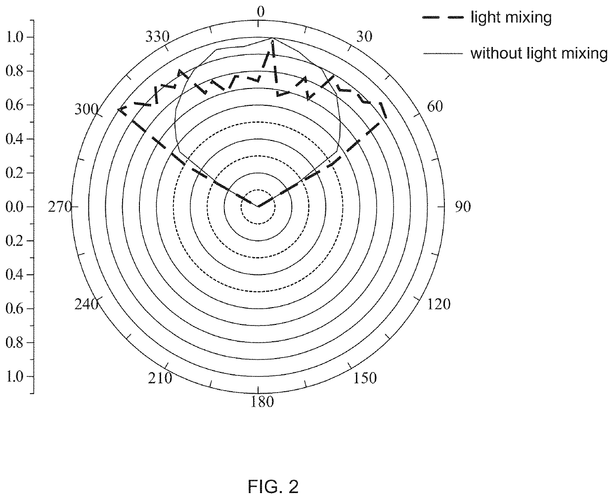
However, due to an influence of light shape and arrangement of the Mini-LEDs, the surface light source may have drawbacks such as uneven brightness of an inner surface of the Mini-LEDs, low brightness at a front side of the Mini-LEDs, and a light utilization rate lower than that of the conventional edge light backlight module.
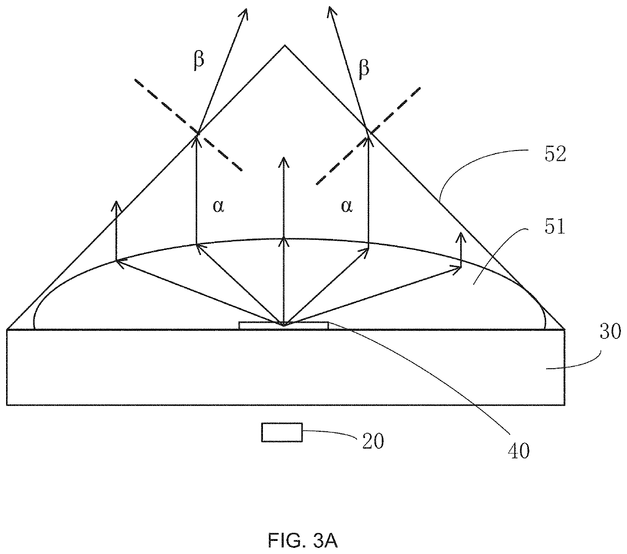
Light with small angle will cause multiple reflections in the conventional prism sheet, and that causes the front side of the surface light source of the Mini-LEDs low in brightness.

Method used


Image

  • Backlight module and liquid crystal display device
  • Backlight module and liquid crystal display device
  • Backlight module and liquid crystal display device

Examples


Embodiment Construction

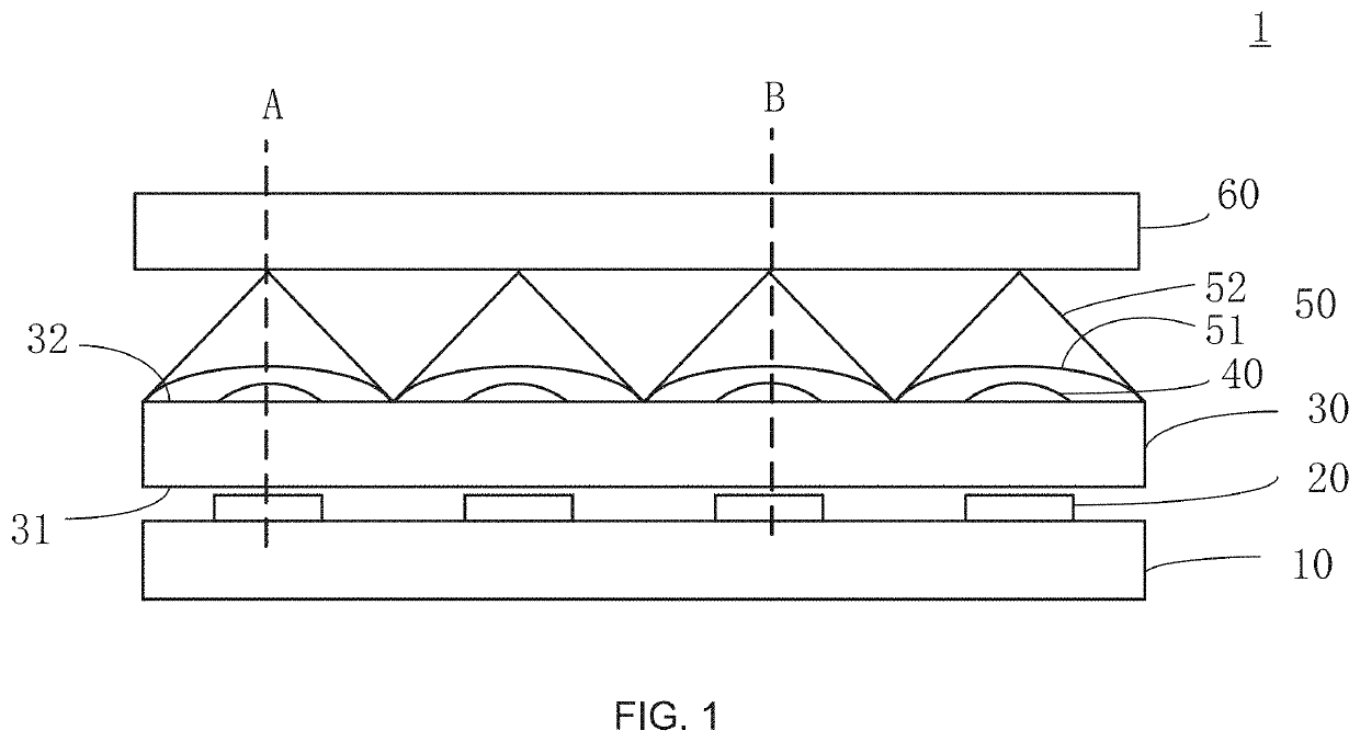
[0036]This description of the exemplary embodiments is intended to be read in connection with the accompanying drawings, which are to be considered part of the entire written description. In the description, terms such as “lower”, “upper”, “horizontal”, “vertical”, “above”, “below”, “up”, “down”, “top”, and “bottom”, as well as derivatives thereof, should be construed to refer to the orientation as then described or as shown in the drawings under discussion. These terms are for convenience of description, and do not require that the apparatus to be constructed or operated in a particular orientation, and do not limit the scope of the disclosure. Referring to the drawings of the disclosure, similar elements are labeled by the same number. The embodiments of the disclosure are described in detail below with reference to the accompanying drawings.

[0037]For a conventional prism structure, a cross section of the conventional prism structure is usually an isosceles right triangle, which i...


PUM

PropertyMeasurementUnit
widthaaaaaaaaaa
heightaaaaaaaaaa
light-emitting angleaaaaaaaaaa

Abstract

A backlight module is provided. The backlight module includes a substrate; a plurality of light emitting elements disposed on the substrate; an optical film disposed on the plurality of light emitting elements; a plurality of light mixing microstructures disposed on the optical film, positions of the light mixing microstructures corresponding to positions of the plurality of light emitting elements; and a plurality of concentrating microstructures correspondingly disposed on the plurality of light mixing microstructures, wherein positions of the plurality of concentrating microstructures correspond to the positions of the plurality of light emitting elements. A liquid crystal display (LCD) device including the backlight module is also provided.

Description

FIELD OF INVENTION[0001]This disclosure relates to display technology, and particularly to a backlight module, and a liquid crystal display device.BACKGROUND OF INVENTION[0002]A liquid crystal display (LCD) panel does not have a light emitting function itself. Therefore, a backlight module must be disposed below the liquid crystal display panel to provide a surface light source to the LCD panel. Light emitting diodes (LEDs) have been widely used in backlight modules because of their high brightness, low power consumption, long life, and less thermal problems.[0003]Mini-LEDs, as a surface light source and a backlight module, include many advantages, such as being light weight and thin, flexible, bendable, high brightness, low power consumption, and the like. Mini-LEDs can overcome a limitation of a light-mixing distance in a conventional edge light backlight module. By manufacturing a narrow border full screen, a partition control display of the backlight module can be realized, and ...

Claims


Application Information

Patent Timeline
Patent Type & Authority Applications(United States)
IPC IPC(8): G02F1/1335
CPCG02F1/133606G02F2001/133607G02F1/133611G02F1/133603G02F1/133607
Inventor YANG, YONG
Owner WUHAN CHINA STAR OPTOELECTRONICS TECH CO LTD
Learn More