Thermoelectric module

a technology of thermoelectric modules and modules, applied in the direction of thermoelectric device details, thermoelectric device manufacturing/treatment, thermoelectric device junction materials, etc., can solve the problems of heat diffusion of the material of a joining layer, etc., to prevent the oxidation and deformation of a thermoelectric element, prevent the heat diffusion of the material, and excellent thermal and electrical properties

Active Publication Date: 2020-04-23
LG CHEM LTD
View PDF0 Cites 0 Cited by
  • Summary
  • Abstract
  • Description
  • Claims
  • Application Information

AI Technical Summary

Benefits of technology

[0023]According to the present invention, a thermoelectric module that comprises a barrier layer having excellent thermal, electrical properties, thereby preventing heat diffusion of the material of a joining layer, preventing the oxidation and deformation of a thermoelectric element under high temperature environment, and exhibiting improved operational stability due to excellent adhesion to a thermoelectric element, can be provided.

Problems solved by technology

In general, a thermoelectric conversion element using Bi-Te-based thermoelectric material is used at a temperature region of about 200˜300° C., and a thermoelectric conversion element using Co-Sb-based thermoelectric material is used at a temperature region of about 500˜600° C. As such, since it is used at high temperature, problems occur in terms of heat diffusion of the material of a joining layer, or the oxidation and deformation of a thermoelectric element.

Method used


Image

  • Thermoelectric module

Examples


example 1

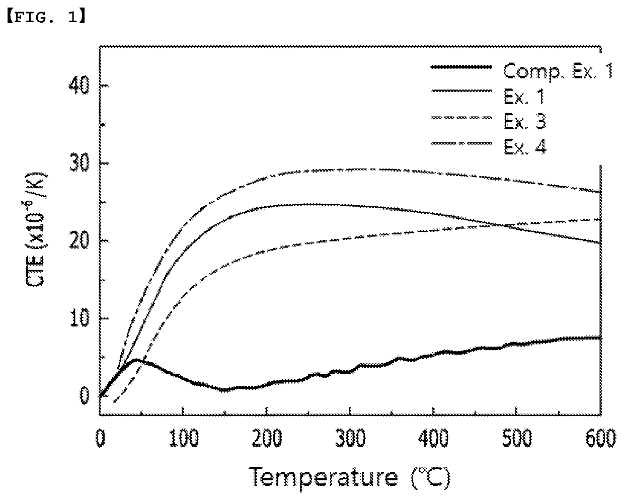
[0056]On a thermoelectric element comprising Bi-Ti-based thermoelectric semiconductor, a barrier layer of Cu—Mo—Ti alloy was deposited through sputtering (the thickness of the barrier layer: 350 nm, the composition of the Cu—Mo—Ti alloy: Cu 12.5 atom %, Mo 70 atom %, Ti 17.5 atom %).

[0057]The thermoelectric element on which a barrier layer is formed was cut to a size of 3×3 mm2 to prepare a die, which was then lead bonded to Au plated Cu substrate, thus manufacturing a thermoelectric module.

[0058]Here, the size of the high temperature substrate of the manufactured thermoelectric module was 30*30 mm, and the size of the low temperature substrate was 30*32 mm, the size of the element was 3*3*2 mm and the thermoelectric module included 32 pairs of the elements.

example 2

[0059]A thermoelectric module was manufactured by the same method as Example 1, except that the thickness of the barrier layer was changed to 160 nm in Example 1.

example 3

[0060]A thermoelectric module was manufactured by the same method as Example 2, except that a barrier layer was formed using Cu—Mo—Ti alloy comprising 25atom % of Cu, 43atom % of Mo and 32atom % of Ti instead of the Cu—Mo—Ti alloy of Example 2.


PUM


Abstract

A thermoelectric module including at least a first and a second thermoelectric element comprising a thermoelectric semiconductor; an electrode connecting the first and second thermoelectric elements; and at least a first and a second joining layer, the first joining layer positioned between the first thermoelectric element and the electrode, and the second joining layer positioned between the second thermoelectric element and the electrode; and at least a first and a second barrier layer including an alloy including Cu, Mo and Ti, the first barrier layer positioned between the first thermoelectric element and the first joining layer, and the second barrier layer positioned between the second thermoelectric element and the second joining layer. The module prevents heat diffusion of the material of the joining layer, preventing the oxidation and deformation of the thermoelectric element under high temperature environment, and exhibiting improved operational stability due to excellent adhesion to a thermoelectric element.

Description

CROSS-REFERENCE TO RELATED APPLICATION(S)[0001]This application claims the benefit of Korean Patent Application No. 10-2017-0040553 filed on Mar. 30, 2017 with the Korean Intellectual Property Office, the disclosures of which are herein incorporated by reference in their entirety.TECHNICAL FIELD[0002]The present invention provides a thermoelectric module in which heat diffusion of the material of a joining layer is prevented, the oxidation and deformation of a thermoelectric element under high temperature environment is prevented, and improved operational stability is exhibited due to excellent adhesion to a thermoelectric element.BACKGROUND ART[0003]If there is a temperature difference between both ends of solid material, a difference in the concentration of heat-dependent carriers (electrons or holes) is generated, which is exhibited as an electrical phenomenon of thermoelectric power, namely, a thermoelectric effect. The thermoelectric effect means reversible and direct energy co...

Claims


Application Information

Patent Timeline
Patent Type & Authority Applications(United States)
IPC IPC(8): H01L35/20H01L35/08
CPCH01L35/34H01L35/20H01L35/08H10N10/817H10N10/855H10N10/851H10N10/852H10N10/853H10N10/01H10N10/854H10N10/82
Inventor KIM, SU JINLEE, IL HAPARK, PUM SUKOH, HYUNGJUKIM, DONG SIKLIM, BYUNG KYUKIM, KI HWANPARK, CHEOL HEE
Owner LG CHEM LTD
Why Eureka
Try Eureka