Ultrasonic Horn With A Large High-Amplitude Output Surface

a high-amplitude output and ultrasonic technology, applied in the field of ultrasonic generators, can solve the problems of increasing vibration amplitudes, increasing the size of the output tip diameter, and the size of the output surface area, so as to maximize the transfer efficiency of ultrasonic generators, increase the available output radiation surface and the uniform distribution of acoustic energy, and increase the effect of acoustic energy radiation

Active Publication Date: 2020-04-30
INDAL SONOMECHANICS
View PDF0 Cites 0 Cited by
  • Summary
  • Abstract
  • Description
  • Claims
  • Application Information

AI Technical Summary

Benefits of technology

[0009]It is therefore a principal object and advantage of the present invention to provide a high-capacity ultrasonic processor that increases the total amount of acoustic energy radiated into a liquid medium by the ultrasonic processor.
[0010]It is an additional object and advantage of the present invention to provide a high-capacity ultrasonic processor that increases the available output radiation surface and the uniformity of the distribution of acoustic energy throughout the volume of the ultrasonic processor.
[0011]It is a further object and advantage of the present invention to provide a high-capacity ultrasonic processor that increases the intensity of acoustic energy radiated into a liquid medium by the ultrasonic processor.
[0012]It is another object and advantage of the present invention to provide a high-capacity ultrasonic processor that maximizes the transfer efficiency of the ultrasonic generator's electric energy into the acoustic energy radiated into a liquid medium by the ultrasonic processor.
[0013]It is an additional object and advantage of the present invention to provide a high-capacity ultrasonic processor that improves the quality of operation and to increase the operational lifespan of the ultrasonic horn incorporated in the ultrasonic processor.
[0014]It is a further object and advantage of the present invention to provide a high-capacity ultrasonic processor that maximizes the production capacity of the ultrasonic processor.

Problems solved by technology

While converging horns may have high gain factors (and, therefore, can significantly increase vibration amplitudes), their high-amplitude output tip diameters and the related output surface areas are too small to deposit sufficient amounts of acoustic energy into liquids to allow for industrial-scale processing.
These devices are, therefore, limited to laboratory-scale processing only.
This provides greater flexibility for designing ultrasonic horns with high output vibration amplitudes and large output surface areas, but still requires interconnecting cylindrical and variable-diameter sections, which elevates stress and reduces the longevity of these devices.
In addition, the requirement for a certain number, types and interconnection sequence of sections complicates the manufacturing of these devices and restricts the designer's ability to adapt their overall shapes to the requirements of a particular sonochemical or sonomechanical process.

Method used


Image

  • Ultrasonic Horn With A Large High-Amplitude Output Surface
  • Ultrasonic Horn With A Large High-Amplitude Output Surface
  • Ultrasonic Horn With A Large High-Amplitude Output Surface

Examples


first embodiment

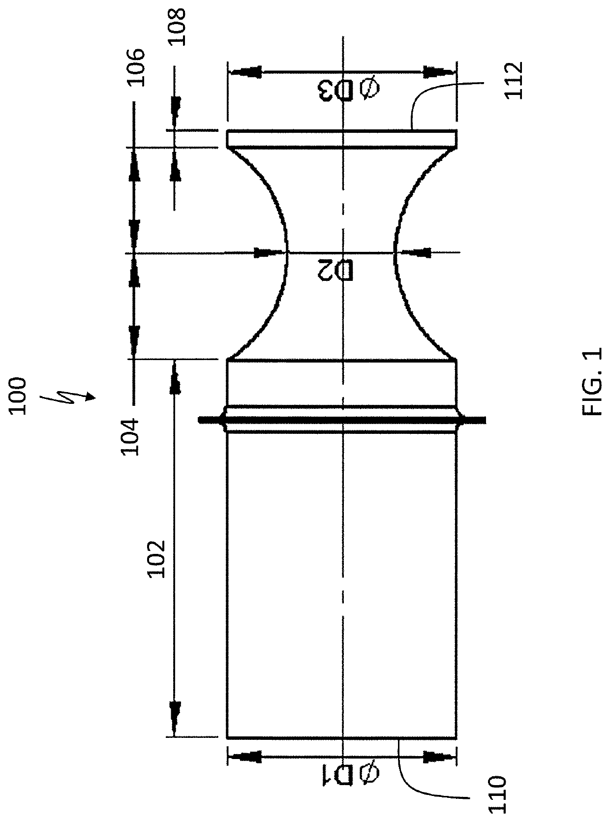
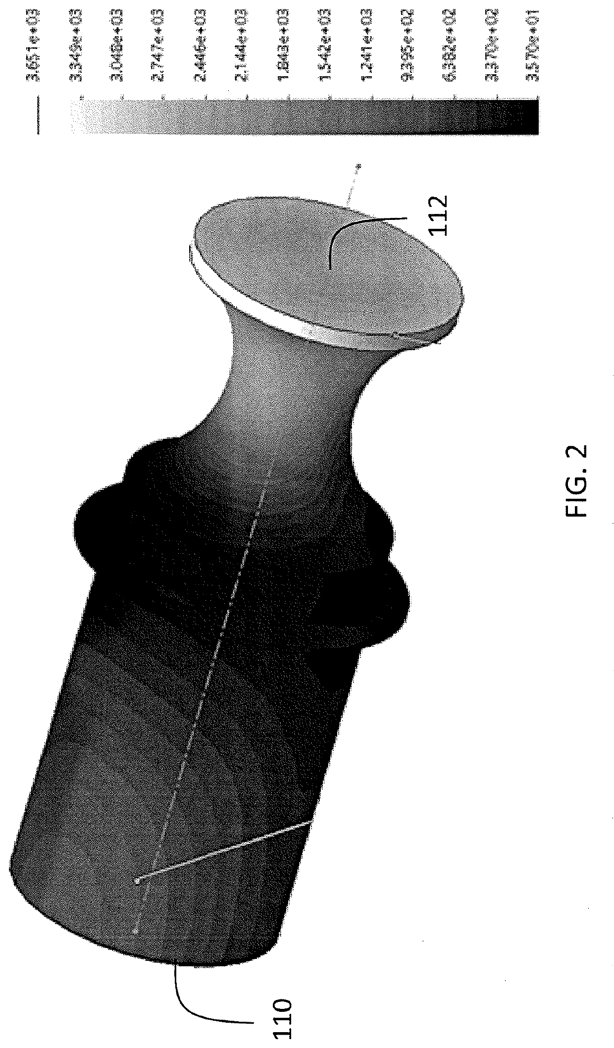
[0026]Referring to the figures, wherein like numeral refer to like parts throughout, there is seen in FIG. 1 an ultrasonic horn 100 which comprises an entrance cylindrical section 102 having a first diameter D1, connected to a first variable-diameter section 104 with a diminishing diameter to a second diameter D2 (hereinafter referred to as “reducing-diameter section”), connected to a second variable-diameter section 106 with an increasing diameter (hereinafter referred to as “increasing-diameter section”) to diameter D3, connected to an exit cylindrical section 108. FIG. 2 shows the ultrasonic amplitudes for horn 100 in arbitrary units and demonstrates a high gain at the output surface 112 of horn 100. In this embodiment, entrance cylindrical section 102 provides the input surface 110 for ultrasonic energy from a transducer, and cylindrical section 108 provides the main output surface 112 from which the energy is transmitted to a fluid in which the output surface is submerged.

second embodiment

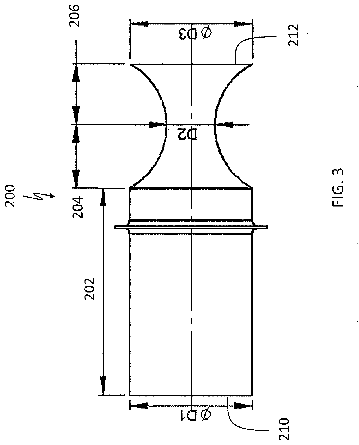
[0027]There is seen in FIG. 3 an ultrasonic horn 200 which comprises an entrance cylindrical section 202 having diameter D1, connected to a reducing-diameter section 204 to a second diameter D2, connected to an increasing-diameter section 206 to diameter D3. FIG. 4 shows the ultrasonic amplitudes for horn 200 in arbitrary units and demonstrates a high gain at the output surface of horn 200. In this embodiment, entrance cylindrical section 202 provides the input surface 210 for ultrasonic energy from a transducer, and increasing-diameter section 206 provides the main output surface 212 from which the energy is transmitted to a fluid in which the output surface is submerged.

third embodiment

[0028]There is seen in FIG. 5 an ultrasonic horn 300 which comprises an entrance cylindrical section 302 of diameter D1, connected to a reducing-diameter section 304 to diameter D2, connected to a thinner intermediate cylindrical section 310 of diameter D2, connected to an increasing-diameter section 306 to diameter D3. FIG. 6 shows the ultrasonic amplitudes for horn 300 in arbitrary units and demonstrates a high gain at the output surface of horn 300. In this embodiment, entrance cylindrical section 302 provides the input surface 310 for ultrasonic energy from a transducer, and increasing-diameter section 306 provides the main output surface 312 from which the energy is transmitted to a fluid in which the output surface is submerged.

[0029]Ultrasonic horn 100, horn 200, or horn 300 of the present invention may be manufactured from the same materials as existing ultrasonic horns, such as titanium alloys and other metals.

[0030]There is seen in FIG. 7, a batch system 400 having an ultr...


PUM


Abstract

Ultrasonic horns having improved longevity and simplified manufacturing approaches that can be more easily adapted to ultrasonic reactor chambers or batch processing containers. The ultrasonic horn designs increase the uniformity and intensity of acoustic energy radiated into a liquid medium and thus better correspond to the requirements of a particular sonochemical or sonomechanical process. The ultrasonic horns do not require a specific number of cylindrical sections and allow for various lengths and profiles of variable-diameter sections. The ultrasonic horns also reduce stress in the material of the ultrasonic horns and therefore extend longevity.

Description

CROSS-REFERENCE TO RELATED APPLICATION[0001]The present application claims priority to U.S. Provisional Application No. 62 / 752,046, filed on Oct. 29, 2018.BACKGROUND OF THE INVENTION1. Field of the Invention[0002]The present invention relates to the field of ultrasonic liquid processing equipment and, more specifically, devices for the transmission of ultrasonic energy into liquid media.2. Description of the Related Art[0003]Advantages of using ultrasonically induced acoustic cavitation for liquid processing are well-known and described, for example, in: K. S. Suslick, Sonochemistry, Science 247, pp. 1439-1445 (1990); T. J. Mason, Practical Sonochemistry, A User's Guide to Applications in Chemistry and Chemical Engineering, Ellis Norwood Publishers, West Sussex, England (1991), hereby incorporated by reference.[0004]In ultrasonic systems designed for industrial liquid processing, the liquid subjected to ultrasonic cavitation treatment is placed in a fixed-volume container (batch pro...

Claims


Application Information

Patent Timeline
Patent Type & Authority Applications(United States)
IPC IPC(8): B01J19/10
CPCB01J2219/0877B01J19/10
Inventor PESHKOVSKY, ALEXEY S.
Owner INDAL SONOMECHANICS
Why Eureka
Try Eureka