High capacity ultrasonic reactor system

a reactor system and ultrasonic technology, applied in the direction of generator/motor, mechanical vibration separation, instruments, etc., can solve the problems of limiting the ability of ultrasonic generators to create powerful ultrasonic cavitation fields, increasing always at the expense of output surface areas, etc., to maximize the transfer efficiency of ultrasonic generators, increase the available radiation surface and the uniform distribution of acoustic energy, and increase the intensity of acoustic energy radiated

Active Publication Date: 2014-02-18
INDAL SONOMECHANICS
View PDF5 Cites 46 Cited by
  • Summary
  • Abstract
  • Description
  • Claims
  • Application Information

AI Technical Summary

Benefits of technology

[0014]It is therefore a principal object and advantage of the present invention to provide a high-capacity ultrasonic reactor system that increases the total amount of acoustic energy radiated into a liquid medium by the ultrasonic reactor system.
[0015]It is an additional object and advantage of the present invention to provide a high-capacity ultrasonic reactor system that increases the available radiation surface and the uniformity of the distribution of acoustic energy throughout the volume of an ultrasonic reactor system.
[0016]It is a further object and advantage of the present invention to provide a high-capacity ultrasonic reactor system that increases the intensity of acoustic energy radiated into the liquid medium of an ultrasonic reactor system.
[0017]It is another object and advantage of the present invention to provide a high-capacity ultrasonic reactor system that maximizes the transfer efficiency of the ultrasonic generator's electric energy into the acoustic energy radiated into the liquid medium.
[0018]It is an additional object and advantage of the present invention to provide a high-capacity ultrasonic reactor system that improves the quality of operation and to increase the operational lifespan of the ultrasonic horn incorporated in the ultrasonic reactor system.
[0019]It is a further object and advantage of the present invention to provide a high-capacity ultrasonic reactor system that maximizes the production capacity of the ultrasonic reactor system.

Problems solved by technology

The horn is used to amplify the transducer's vibration amplitude, which is necessary because the vibration amplitude of the transducer itself is not sufficient for most industrial processes.
All of the abovementioned systems possess an important common drawback, which restricts their ability to create powerful ultrasonic cavitation fields and limits their production capacity.
This drawback stems from the fact that the acoustic horns used in the prior art generally have tapered shapes, such as conical, exponential, catenoidal, stepped, or more complex, converging in the direction of the load.
While these horns may have high gain factors and permit significantly increasing vibration amplitudes, the increase occurs always at the expense of the output surface areas, which become small as a result.
Therefore, while converging horns are capable of increasing the specific acoustic power (or vibration amplitude at a given ultrasonic frequency) radiated by a transducer into a load quite effectively, they do not permit achieving significant levels of total radiated acoustic power.
The total power provided by a generator and a transducer is, therefore, not efficiently transmitted into the liquid (reflected back).
Success of industrial applications of such systems is limited.
Additionally, in the design of the abovementioned ultrasonic reactors, the size and shape of the cavitation field itself is not taken into account, which further lowers their efficiency.
The prior art “Barbell Horn”, its derivatives as well as the related ultrasonic reactor designs, however, are subject to some important limitations.
The design principles and the calculation method for the horns which are free from this restriction were not available and are not provided in the prior art.
All these additional elements significantly complicate the construction of the Barbell Horns, introduce additional mechanical connections and, therefore, reduce life span and reliability.
It is also clear that utilizing the Barbell Horns or any of their modified versions in a non-restricted or an incorrectly restricted volume (reactor chamber) leads to an inefficient process, since not all liquid is put through the well developed cavitation field zone and / or the optimal treatment time in the cavitation field is not reached.

Method used


Image

  • High capacity ultrasonic reactor system
  • High capacity ultrasonic reactor system
  • High capacity ultrasonic reactor system

Examples


embodiment 1

[0067]Catenoidal Barbell Horn

[0068]U.S. Pat. No. 7,156,201 provides a system of equations that is suitable only for calculating the Barbell Horns (or Transducer Barbell Horn Assemblies) with cone-shaped transitional sections (parts of the horns that have changing cross-sections). Additionally, a restriction exists in the description and in the claims of the same prior art, requiring that the length of any transitional section be equal or greater than Log(N) / k, where k=ω / C is the wave number, N is the ratio of the diameters of the thick and the thin cylindrical sections that are adjacent to the transitional section, ω is the angular vibration frequency, C is the sound velocity in the horn material at the transitional section (with phase velocity dispersion taken into account). This restriction came from the fact that the specified length of the transitional section is critical from the standpoint of the passage of a longitudinal acoustic wave. Such selection of the length of the tran...

first embodiment

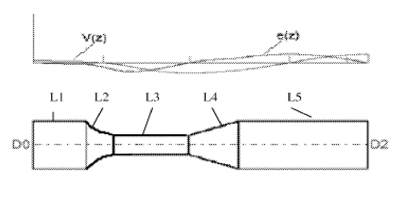
[0070]The following example provides clarification of the abovementioned theoretical explanation. Catenoidal Barbell Horn was calculated for the operation frequency of 20 kHz, having catenoidal first transitional section of the length significantly smaller than the value Log(N) / k. FIG. 1 shows a Catenoidal Barbell Horn according to the present invention, where V(z)—distribution of the amplitude of vibration velocity along the horn length, e(z)—distribution of the deformation along the horn length, with lengths L1-L5 representing the lengths of the corresponding horn elements, respectively. In a preferred embodiment, the Catenoidal Barbell Horn has the following lengths: L1=54.33 mm, L2=20.61 mm, L3=54.33 mm, L4=41.22 mm, L5=106.71 mm, Gain=5.16, D0=D2=50 mm, Freq=20 kHz, and is made from 2024 aluminum. It can be seen from the figure that although the transitional section L2 is significantly shorter than Log(N) / k, the deformation change along the horn is smooth and continuous, withou...

embodiment 2

[0071]Catenoidal Transducer-Barbell Horn Assembly

[0072]Barbell Horn incorporating an active acoustic transducer for converting electric energy into acoustic energy was described in U.S. Pat. No. 7,156,201. In this device, piezoelectric annular transducers are situated in the Barbell Horn close to the node locations, and, because the utilized Barbell Horn has a gain factor greater than unity, the amplitude of the vibrations at the output end of the assembly is much higher than the amplitude of the vibrations of the piezoelectric annular transducers themselves.

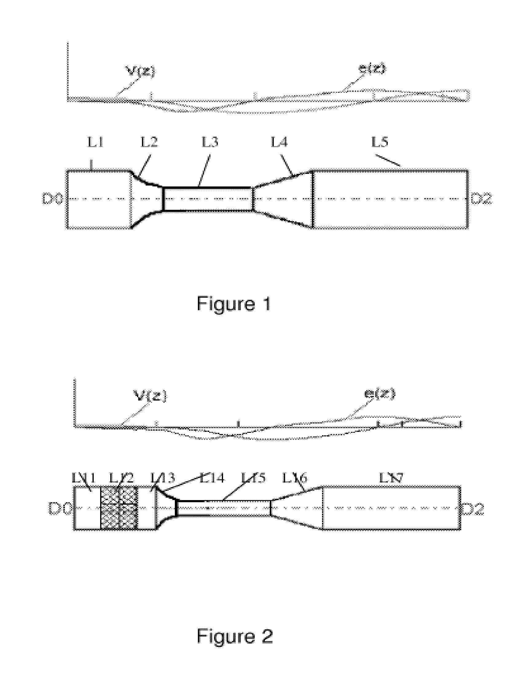
[0073]The first transitional section of this device, however, was limited to having a conical shape and the length equal or greater than the value Log(N) / k (Conical Transducer-Barbell Horn Assembly). In the present invention, a Catenoidal Transducer-Barbell Horn Assembly is introduced, having catenoidal first transitional section of the length significantly smaller than the value Log(N) / k. FIG. 2 shows this assembly along with t...


PUM


Abstract

An ultrasonic reactor system with an appropriately designed reactor chamber used in conjunction with a compatible ultrasonic Barbell Horn or its derivative that provides a significant efficiency increase and an intensification of sonochemical and sonomechanical processes is disclosed. These enhancements arise from the ability of the reactor chamber to direct all treated liquid media through the highly active ultrasonic cavitation region located near the surface of the horn, as well as from several improvements in the Barbell Horn design that significantly increase its longevity and in its output surface area, thereby increasing the total size of the active cavitation region.

Description

CROSS-REFERENCE TO RELATED APPLICATION[0001]The present application claims priority to PCT Number PCT / US2008 / 068697 which claims priority to U.S. Provisional Application No. 60 / 947,768, filed Jul. 3, 2007.BACKGROUND OF THE INVENTION[0002]1. Field of the Invention[0003]The present invention relates to the field of ultrasonic equipment and, more specifically, systems for the transmission of acoustic energy into liquid media during acoustic cavitation-based sonochemical and sonomechanical processes.[0004]2. Description of the Related Art[0005]Advantages of using ultrasonically induced acoustic cavitation to carry out technological processes in liquids are well documented, for example, in the following references: K. S. Suslick, Sonochemistry, Science 247, pp. 1439-1445 (1990); T. J. Mason, Practical Sonochemistry, A User's Guide to Applications in Chemistry and Chemical Engineering, Ellis Norwood Publishers, West Sussex, England (1991), hereby incorporated by reference.[0006]In the pri...

Claims


Application Information

Patent Timeline
Patent Type & Authority Patents(United States)
IPC IPC(8): A61B17/20G08B3/02H03H9/00
CPCB01J19/008B01J19/10B06B3/00
Inventor PESHKOVSKY, SERGEI L.PESHKOVSKY, ALEXEY S.
Owner INDAL SONOMECHANICS
Why Eureka
Try Eureka