
LED lighting device and dimming control method therefor

a technology of led lighting and control method, which is applied in the direction of basic electric elements, electroluminescent light sources, electric apparatus, etc., can solve the problems of failure of one led lighting device to not be spread to other led lighting devices, high circuit complexity, and secondary damage, so as to reduce the production cost of the led lighting device, the effect of high accuracy and isolation

Active Publication Date: 2020-05-07
LG INNOTEK CO LTD
View PDF3 Cites 2 Cited by
  • Summary
  • Abstract
  • Description
  • Claims
  • Application Information

AI Technical Summary

Benefits of technology

The present invention allows for a simple structure and high accuracy and isolation in dimming circuits using a small number of switching elements. This makes it easy to dim LED lights and reduces production costs. The accuracy of dimming is not affected by the inductance value of the transformer, which can be designed to be low, allowing for the use of a smaller transformer.

Problems solved by technology

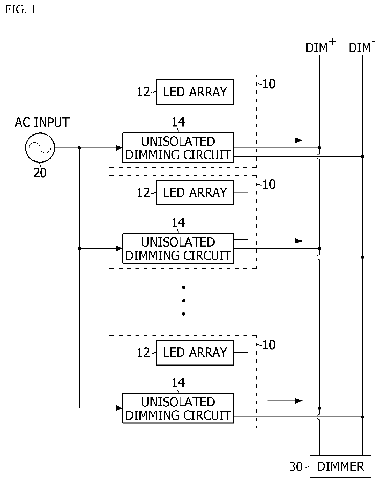
Accordingly, since the failure is spread to other LED lighting devices 10 which stably operate, secondary damage can occur.
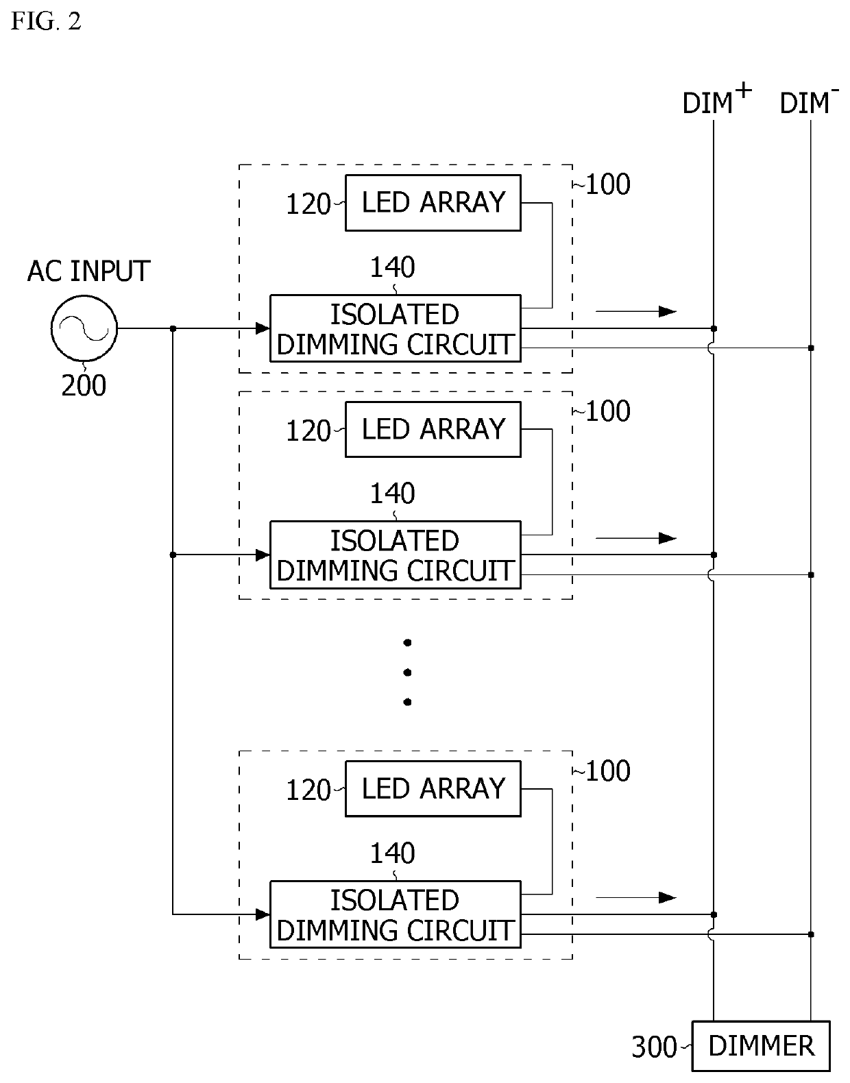
The dimming circuit having the isolation structure includes an isolation transformer which isolates a primary coil of an LED array and a secondary coil of a dimmer, and accordingly, the failure which occurs from the one LED lighting device may not be spread to other LED lighting devices.
Meanwhile, a dimming circuit having a general isolation structure uses a plurality of semiconductor elements, and thus has high circuit complexity, and it is difficult to accurately control dimming thereof.
Further, since large inductance is demanded and thus the size of an isolation transformer increases, cost efficiency and space efficiency are low.

Method used


Image

  • LED lighting device and dimming control method therefor
  • LED lighting device and dimming control method therefor
  • LED lighting device and dimming control method therefor

Examples


Embodiment Construction

[0026]Hereinafter, preferable embodiments of the present invention will be described in detail with reference to the accompanying drawings.

[0027]However, the technical spirit of the present invention is not limited to some embodiments which will be described and may be embodied in various forms, and one or more elements in the embodiments may be selectively combined and replaced to be used within the scope of the technical spirit of the present invention.

[0028]Further, terms used in the embodiments of the present invention (including technical and scientific terms), may be interpreted with meanings that are generally understood by those skilled in the art unless particularly defined and described, and terms which are generally used, such as terms defined in a dictionary, may be understood in consideration of their contextual meanings in the related art.

[0029]In addition, terms used in the description are provided not to limit the present invention but to describe the embodiments.

[00...


PUM


Abstract

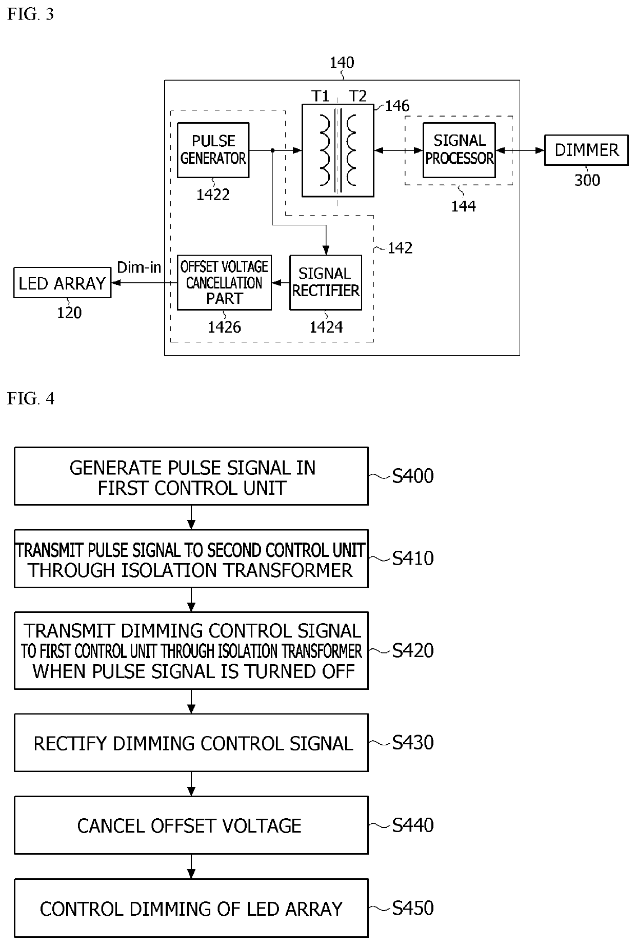
An LED lighting device according to one embodiment of the present invention comprises: an LED array; a first control unit for controlling the dimming of the LED array; a second control unit for transmitting, to the first control unit, a dimming control signal for controlling the dimming of the LED array; and a transformer comprising a primary coil and a secondary coil spaced apart from each other, wherein the first control unit is connected to the primary coil, the second control unit is connected to the secondary coil, the primary coil and the secondary coil are insulated from each other, the transformer transmits a pulse signal that repeats on / off at predetermined intervals from the first control unit to the second control unit, and, when the pulse signal transmitted from the first control unit to the second control unit via the transformer becomes off, the dimming control signal is transmitted from the second control unit to the first control unit via the transformer and is used to control the dimming of the LED array.

Description

TECHNICAL FIELD[0001]The present invention relates to a light emitting diode (LED) lighting device, and more specifically, to a dimming control method of an LED lighting device.BACKGROUND ART[0002]A fluorescent lamp, an incandescent lamp, a light emitting diode (LED), and the like are used as indoor and outdoor lighting devices. Among the above, the lighting device using the LED has low power consumption and is semi-permanent in comparison with the fluorescent lamp.[0003]FIG. 1 is an example of a lighting system including an LED lighting device.[0004]Referring to FIG. 1, an LED lighting device 10 receives power from a power source 20 and includes an LED array 12 and a dimming circuit 14.[0005]A plurality of LED lighting devices 10 can be controlled by one dimmer 30.[0006]In this case, when a failure occurs due to an overvoltage such as a short circuit or surge to one of the plurality of LED lighting devices 10, the failure is spread to the dimmer 30 through DIM+ and DIM− wires. Acco...

Claims


Application Information

Patent Timeline
Patent Type & Authority Applications(United States)
IPC IPC(8): H05B45/392H05B45/14H01L29/866H05B44/00
CPCH05B45/392H05B45/14H01L29/866H05B45/385H05B45/10H05B45/00Y02B20/30
Inventor JO, JI WOONGLEE, JONG HYUNCHOI, JAE HOKIM, MIN HAKSEO, MIN SUBAEK, SEUNG WAN
Owner LG INNOTEK CO LTD
Learn More