
Oscillator device

a technology of oscillator and oscillator, which is applied in the direction of pulse generator, pulse generation by logic circuit, pulse technique, etc., can solve the problems of not being suitable for applications with prespecified clock pulse rate, precision clock pulse generators generally, and having a relatively large switching time of more than 10 s, and achieve stable clock rate, low impedance, and fast activation of the corresponding electronic circuit

Active Publication Date: 2020-05-14
ROBERT BOSCH GMBH
View PDF6 Cites 0 Cited by
  • Summary
  • Abstract
  • Description
  • Claims
  • Application Information

AI Technical Summary

Benefits of technology

The present invention is about compensating for temperature-dependent frequency fluctuations of a ring oscillator by adjusting the voltage supply to it. This is done by using a temperature sensor element that emulates the temperature effects of the ring oscillator to create a system that compensates for these fluctuations in real-time. Overall, this invention improves the stability and accuracy of the ring oscillator, resulting in better performance and reliability in electronic circuits.

Problems solved by technology

Conventional “free-wheeling” ring oscillators have a very large frequency scatter related to manufacturing process fluctuations and ambient temperature, and are therefore generally not suitable for applications having prespecified clock pulse rates.
Such precision clock pulse generators generally, however, have a relatively large switching time of more than 10 μs.

Method used


Image

  • Oscillator device

Examples


Embodiment Construction

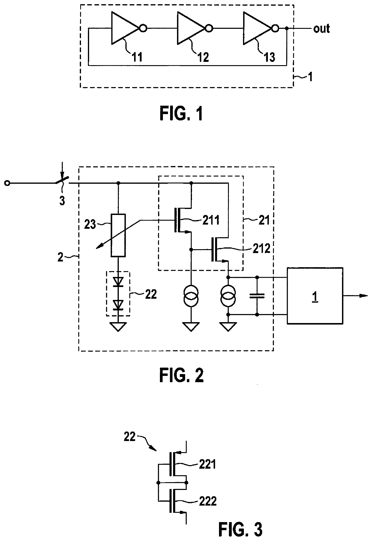
[0024]FIG. 1 shows a schematic representation of a ring oscillator 1 according to a specific embodiment. In the specific embodiment shown here, ring oscillator 1 includes three inverters 11, 12, and 13, that are connected to one another in a ring configuration. In this context, “ring configuration” means that the output of an inverter 11 or 12 is connected to the input of a subsequent inverter 12 or 13. The output of the last inverter 13 is in turn connected to the input of the first inverter 11. The variant shown here, having only three inverters 11, 12, and 13, is intended only as an illustration. In addition, here an arbitrary number of additional inverters, in particular an arbitrary odd number of inverters, is also possible. Due to the finite runtime of the individual inverters 11, 12, and 13, an oscillation will arise after a supply voltage is applied to ring oscillator 1. This oscillation inside ring oscillator 1 can be tapped and conducted outward, so that the oscillation ca...


PUM


Abstract

An oscillator device based on a ring oscillator, in which temperature-dependent fluctuations in the frequency of the clock signal of a ring oscillator can be compensated by adapting the supply voltage of the ring oscillator. For this purpose, the supply voltage of the ring oscillator is adapted as a function of an ambient temperature, using a voltage supply circuit.

Description

FIELD OF THE INVENTION[0001]The present invention relates to an oscillator device. In particular, the present invention relates to a fast-starting oscillator device having a ring oscillator.BACKGROUND INFORMATION[0002]Patent document EP 1347575 A1 discusses a method for producing an oscillating signal having the steps of initializing an even-numbered number of inverters chained to one another, so that the outputs of the inverters have, in an alternating manner, a first logical value and a second logical value, and of inputting an excitation pulse into the chain of inverters in order to excite the oscillation, the length of the excitation pulse being smaller than the runtime through the chain of inverters.[0003]Ring oscillators are believed to be understood. Generally, ring oscillators have an odd number of inverting components wired together in a ring configuration. Due to the finite runtime in the individual inverting components, after application of a supply voltage an at least ap...

Claims


Application Information

Patent Timeline
Patent Type & Authority Applications(United States)
IPC IPC(8): H03K3/03H03K3/011
CPCH03K3/0315H03K3/011
Inventor ROEWER, FALK
Owner ROBERT BOSCH GMBH
Learn More