Arrangement and Method for Detecting Leaks in a Water Pipe System

a leak detection and water pipe technology, applied in the direction of fluid tightness measurement, positive displacement liquid engine, instruments, etc., can solve the problems of affecting the detection accuracy of leakage detection, and inevitably occurring leakage during operation, so as to achieve accurate leakage detection and easy and reliably detection

Active Publication Date: 2020-05-21
VIEGA TECH GMBH & CO KG
View PDF0 Cites 11 Cited by
  • Summary
  • Abstract
  • Description
  • Claims
  • Application Information

AI Technical Summary

Benefits of technology

[0013]Thus, a leakage can be easily and reliably detected and, if necessary, located by means of a differential pressure method, which in particular is carried out periodically. The more finely meshed the valves, shut-off valves and pressure sensors are placed in the water pipe system, the more accurately the leakage can be located.

Problems solved by technology

In water pipe systems or in general in media-carrying systems, leaks inevitably occur during operation.
Leakages are becoming increasingly important because the drinking water network represents the greatest threat to households and buildings.
Especially micro-leaks, such as a dripping water tap with a flow rate of 0.04 l / min, are very difficult to detect due to the small quantity.
With this method small leaks in the wall are not detected at all or very late.
All known systems which detect a leakage by means of pressure and flow are limited to cold water pipes without circulation.
The disadvantages are that the detection and the localization are two different processes, which are differing in time, resulting in a high damage.
In addition, damages, in which only small quantities leak, but over a longer period of time, cannot be registered in this way.

Method used


Image

  • Arrangement and Method for Detecting Leaks in a Water Pipe System

Examples


Embodiment Construction

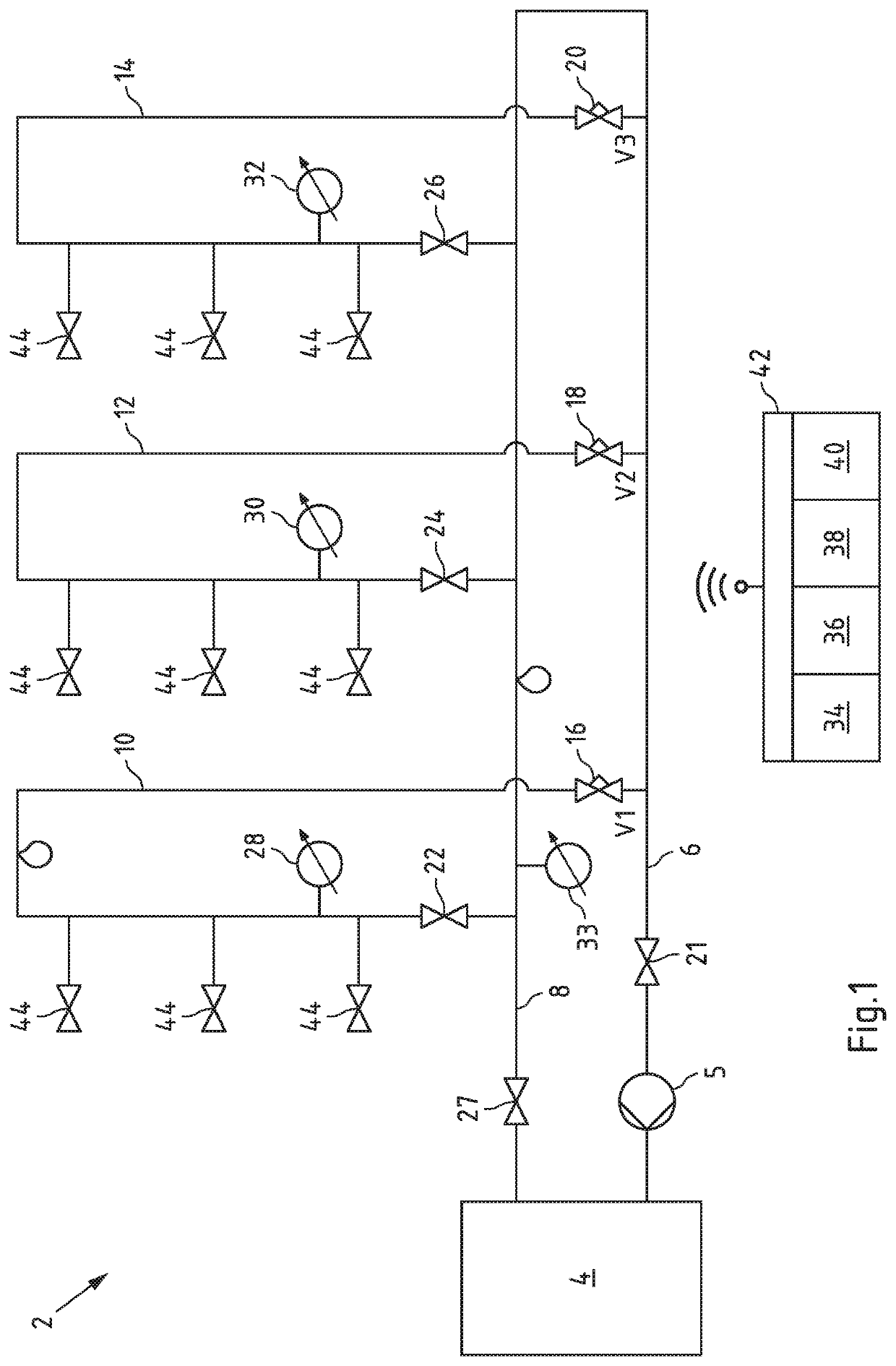
[0027]FIG. 1 shows an arrangement according to invention 2 for detecting and locating a leakage in a water pipe system, with a water treatment 4, which, for example, can be designed as a hot or cold water treatment or as a heat exchanger, in particular a flow-through heat exchanger, and supplies the water pipe system with hot drinking water.

[0028]The arrangement 2 also has a pump 5 as well as a supply line 6 and a drain 8, which are either arranged essentially horizontally on one floor or arranged essentially vertically as risers and downpipes. The supply line 6 is fluidically connected to the drain 8.

[0029]Three circulation lines 10, 12 and 14 are connected to the supply line 6 and the drain 8, each having an inlet valve 16, 18 and 20, an outlet valve 22, 24 and 26 and a pressure sensor 28, 30 and 32. The inlet valves 16, 18 and 20 and the outlet valves 22, 24 and 26 are electrically controllable.

[0030]In addition, an inlet valve 21 in the supply line 6 and an outlet valve 27 in th...


PUM


Abstract

The invention relates to an arrangement for detecting and locating a leakage in a water pipe system, having a water treatment system, having a pump, having a supply line and a drain, having at least one circulation line connected to the supply line and the drain, having at least one inlet valve, at least one outlet valve and at least one pressure sensor in at least one circulation line and/or the supply line and the drain, wherein the inlet valve and the outlet valve are electrically controllable, having control means for controlling the inlet valves and the outlet valves, having detection means for detecting the timewise development of the measured values of the at least one pressure sensor, with evaluation means for evaluating the timewise development of the pressure change and for comparing the amount of the pressure change with a limit value, and with output means for the output of a leakage indicating indication signal if the amount of the pressure change exceeds the limit value. This arrangement solves the technical problem of improving the detection and, if necessary, location of a leakage.

Description

CROSS-REFERENCE TO RELATED APPLICATION[0001]This application claims priority to German Patent Application No. 10 2018 128 855.7 filed Nov. 16, 2018, the disclosure of which is hereby incorporated by reference in its entirety.BACKGROUND OF THE INVENTIONField of the Invention[0002]The invention relates to an arrangement and a method for detecting and, if necessary, locating leaks in a water pipe system.Description of Related Art[0003]In water pipe systems or in general in media-carrying systems, leaks inevitably occur during operation. Leakages are becoming increasingly important because the drinking water network represents the greatest threat to households and buildings. The causes are very diverse, since they are influenced by many parameters and can also differ regionally, e.g. influenced by the water composition. Especially micro-leaks, such as a dripping water tap with a flow rate of 0.04 l / min, are very difficult to detect due to the small quantity.[0004]To prevent damages, mor...

Claims


Application Information

Patent Timeline
Patent Type & Authority Applications(United States)
IPC IPC(8): G01M3/28F04B51/00
CPCF04B51/00G01M3/2815E03B7/071E03B7/003G01M3/40Y02A20/15F24H15/12
Inventor WINTERHOLLER, ARTHURSTÄHLER, BENRISCHEN, CHRISTIAN
Owner VIEGA TECH GMBH & CO KG
Why Eureka
Try Eureka