
Apparatus and method for testing a temperature monitoring substrate

Inactive Publication Date: 2008-09-04
TOKYO ELECTRON LTD
View PDF10 Cites 7 Cited by
  • Summary
  • Abstract
  • Description
  • Claims
  • Application Information

AI Technical Summary

Benefits of technology

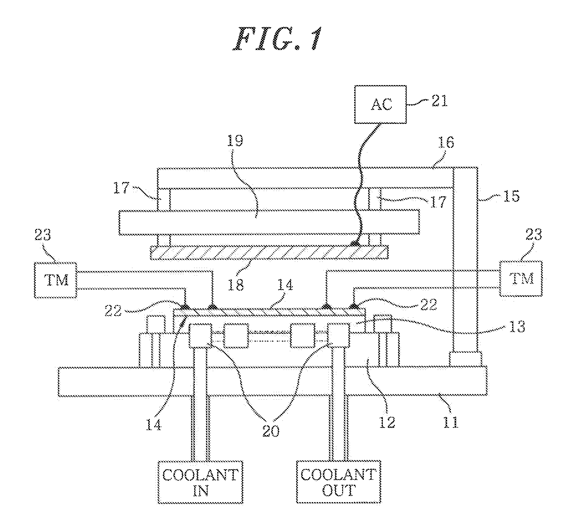
[0017]In view of the foregoing, the invention provides a practical technology that can easily and reliably detect in a nondestructive manner whether or not a residual bubble or a foreign substance, which may cause an error in measuring the temperature, exists at a portion of a temperature monitoring substrate where a temperature sensor is located, without using a large-scale apparatus such as an X-ray apparatus.
[0018]The inventors have studied various technologies to solve the above-described problem, and have found that an installation failure of a temperature sensor can be easily detected by comparing measurement values of at least two thermocouples installed at the same depth, wherein the measurement is performed in a state where a uniform heat flow or temperature distribution is formed in a depthwise direction of a substrate.
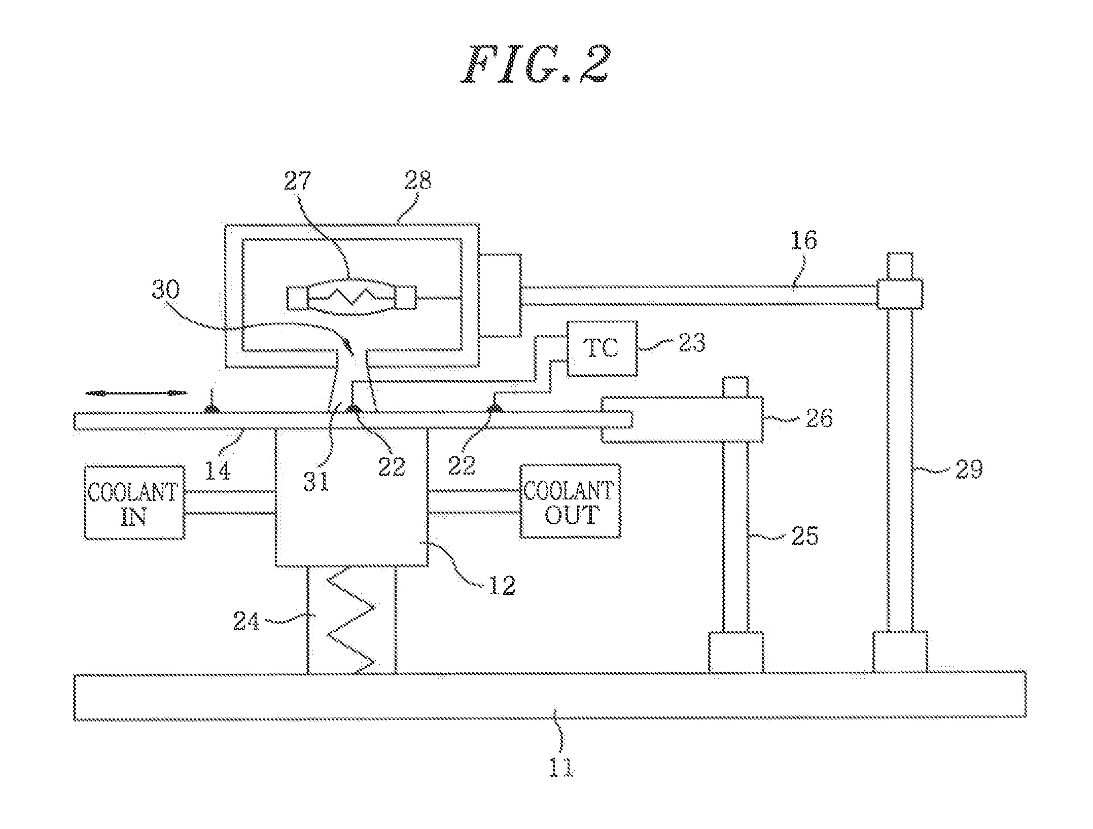
[0024]In this regard, by generating the heat flow only in the regions in and around the temperature sensors, the condition of constant heat flow can be satisfied more easily. Therefore, by shifting the substrate using the transfer unit such that the thermocouples enter the above-mentioned regions one after another, it becomes easier to test the measurement values of the thermocouples under the condition of constant heat flow.
[0032]In accordance with the present invention, it can easily and reliably detected in a nondestructive manner whether or not a residual bubble or a foreign substance, which may cause an error in measuring the temperature, exists at a portion of a temperature monitoring substrate where a temperature sensor is located, without using a large-scale apparatus such as an X-ray apparatus.

Problems solved by technology

However, even though the manufacturers guarantee that the temperature monitoring substrates are accurately adjusted, a noticeable number of temperature monitoring substrates still output erroneous values during an actual semiconductor manufacturing process.
In this case, an abnormality of the temperature sensor itself can be detected.
However, an abnormality due to an improper installation of the temperature sensor to the substrate cannot be detected by such a method.
The improper installation of the temperature sensor may adversely affect the temperature measurement of the substrate during an actual semiconductor manufacturing process.
Therefore, if the adhesive 4 has a higher heat resistance to increase the heat resistance, the fluidity is deteriorated.
Further, a heat transfer from the cooling mechanism 8 is not sufficiently conducted.
Thus, since the temperature of the temperature monitoring substrate is not approximately equal to the wafer temperature during the actual process, the temperature monitoring substrate cannot function properly.
Further, the same problem also occurs if a foreign substance having a low thermal conductivity exists in place of the residual bubble 5.
However, an error in the temperature measurement value caused by the improper installation (hereinafter, simply referred to as “installation failure”) cannot be detected by the conventional method.
Therefore, even if a residual bubble or a foreign substance exists as described above, the temperature at the contact rapidly becomes equal to the substrate temperature therearound, thereby making it difficult to detect an installation failure.
However, since this method requires excessive costs and time, it is not practical.

Method used


Image

  • Apparatus and method for testing a temperature monitoring substrate
  • Apparatus and method for testing a temperature monitoring substrate
  • Apparatus and method for testing a temperature monitoring substrate

Examples


first example

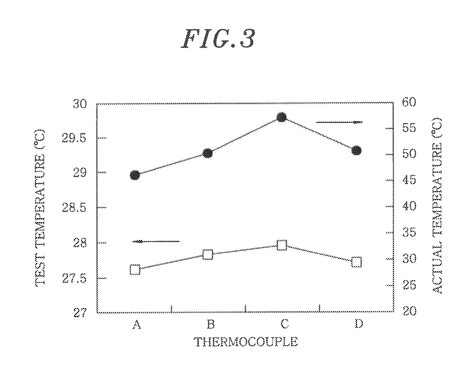
[0056]Using the testing apparatus shown in FIG. 2, temperature measurement was performed on a temperature monitoring substrate to which four thermocouples are installed. Then, while maintaining the substrate in an actual plasma processing apparatus, a temperature measurement was performed during an actual process in which plasma was generated. Subsequently, the temperature indicated by the testing apparatus was compared to the temperature during the actual process. In addition, the deviation of the indicated values of the thermocouples was measured while maintaining the substrate in the thermostat bath. The temperature monitoring substrate to be measured had a diameter of 300 mm and a thickness of 725 μm, and K thermocouples were used. Furthermore, the K thermocouples were arranged at locations distanced from the center by a radius 142 mm and shifted from each other at a degree of 90°, and the K thermocouples were installed at the same depth.

[0057]The measurement results are shown i...

second example

[0058]In the same manner as the first example, a heat flow measurement was performed by the testing apparatus. Then a location of a thermocouple determined to have an installation failure and a location of another thermocouple determined not to have an installation failure were observed by X-ray fluoroscopy. At the thermocouple that was determined to be improperly installed, ΔT (the deviation from the average temperature) was 0.22° C. However, at the thermocouple that was determined to be properly installed, ΔT was 0.16° C. X-ray fluoroscopic images were obtained by obliquely irradiating an X ray onto the substrate at approximately 30° (an inclination degree of 60° with respect to the normal), and diagrams thereof were presented below the photographs, respectively. The X-ray fluoroscopic images and the diagrams thereof are shown in FIG. 4A to FIG. 4D.

[0059]FIGS. 4C and 4D show a case where the thermocouple is properly installed (no installation failure), and FIGS. 4A and 4B show a c...


PUM


Abstract

A testing apparatus for a temperature monitoring substrate includes a heat flow generating unit for generating a heat flow in the temperature monitoring substrate in a depthwise direction of the temperature sensors, wherein the temperature sensors are buried in the depthwise direction. Further, a testing method for a temperature monitoring substrate includes generating a heat flow in the temperature monitoring substrate in a depthwise direction, wherein the temperature sensors are buried in the depthwise direction; processing a temperature of the substrate measured by the temperature sensor under the heat flow by a prescribed method; and determining whether or not an error occurs in the temperature sensor.

Description

FIELD OF THE INVENTION[0001]The present invention relates to an apparatus and a method for testing a temperature monitoring substrate to be used to measure a temperature and / or temperature distribution of a substrate in a semiconductor manufacturing process; and, more particularly, to an apparatus and a method for testing a temperature monitoring substrate that determines whether or not a temperature sensor is properly installed at the substrate.BACKGROUND OF THE INVENTION[0002]During a semiconductor manufacturing process, a substrate, such as a silicon wafer, is subject to a heat treatment, such as oxidization, diffusion, or annealing. Usually, during the heat treatment, the substrate is heated in a furnace. At this time, since a temperature range varies according to the purposes of the heat treatment, it is necessary to monitor the temperature of the substrate to be heated in order that the furnace is maintained at a specific temperature or follows a preset rising or falling rate ...

Claims


Application Information

Patent Timeline
IPC IPC(8): G01K13/02
CPCG01K15/00H01L21/67109G01K15/007
Inventor SASAKI, YASUHARUUEDA, TAKEHIROOKAJO, TAKETOSHI
Owner TOKYO ELECTRON LTD
Learn More