Crude oil stabilization

a technology of crude oil and stabilization, applied in the direction of hydrocarbon distillation, hydrocarbon oil treatment, liquid hydrocarbon mixture production, etc., can solve the problem of inability to build, and achieve the effect of reducing equipment, installation and operation costs, and reducing components

Pending Publication Date: 2020-05-28
TECH PRECESS TECH INC
View PDF3 Cites 3 Cited by
  • Summary
  • Abstract
  • Description
  • Claims
  • Application Information

AI Technical Summary

Benefits of technology

[0012]The embodiments disclosed herein provide for reduced components for and overall size of the stabilization system, thereby reducing equipment, installation and operation costs.

Problems solved by technology

The stabilization process often takes place in areas where available space may be limited, the site may be remote and / or skilled labor may not be available for construction.

Method used


Image

  • Crude oil stabilization
  • Crude oil stabilization

Examples


Embodiment Construction

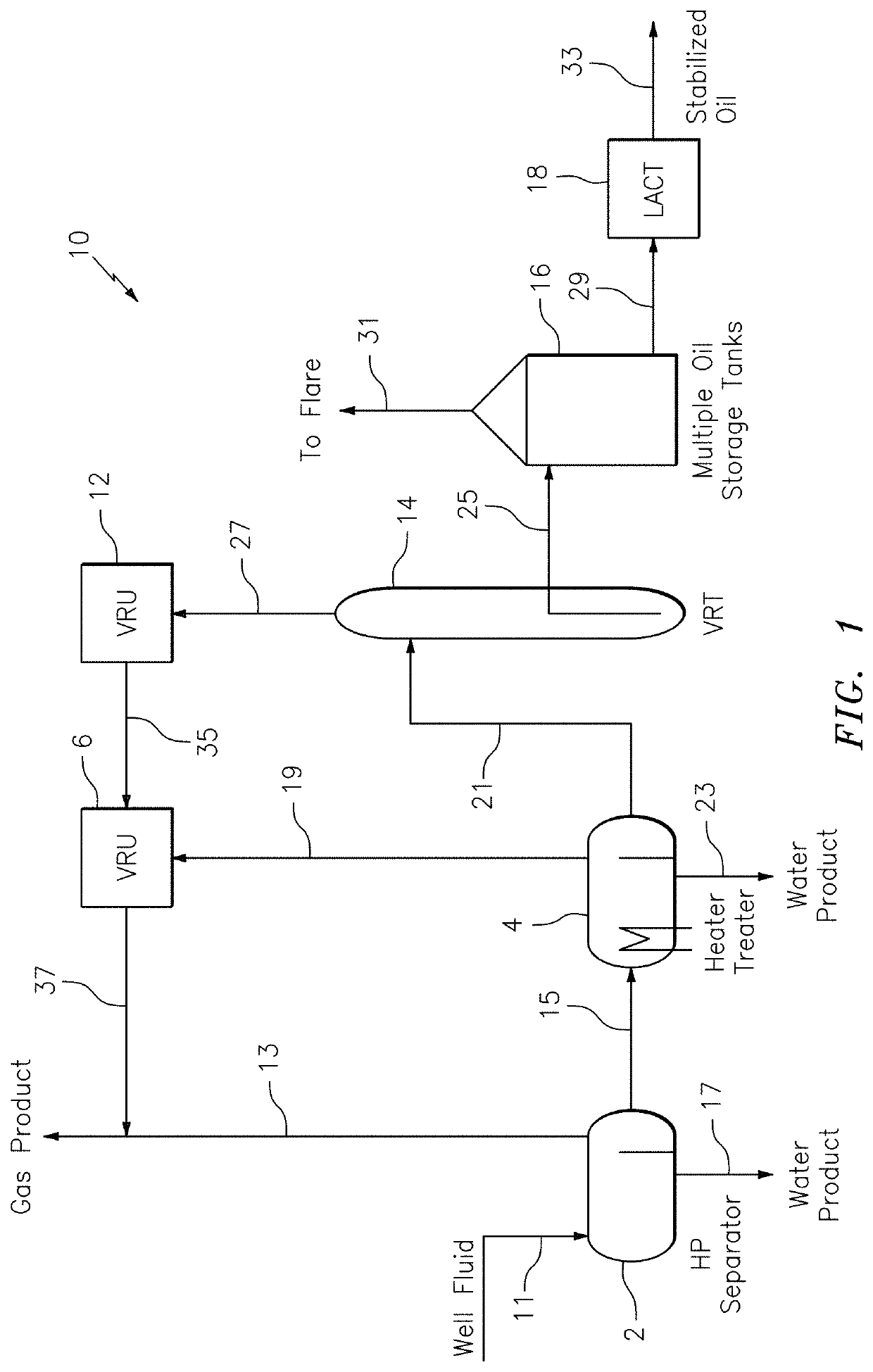
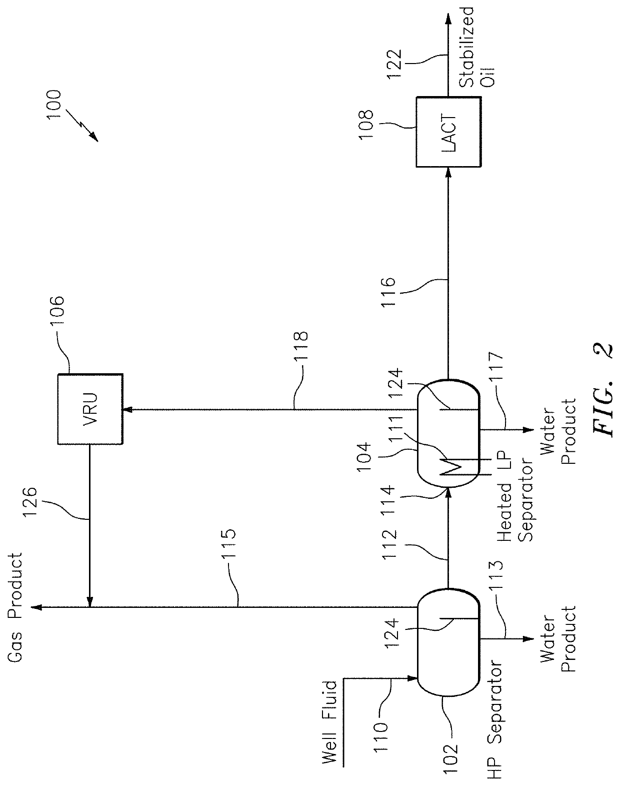
[0017]Reference will now be made to the drawings wherein like reference numerals identify similar structural features or aspects of the subject invention. For purposes of explanation and illustration, and not limitation, a schematic representation of an exemplary embodiment of a stabilization system in accordance with the invention is shown in FIG. 2 and is designated generally by reference character 100. The methods and systems of the invention can be used for more efficient stabilization of crude oil, including shale or tight oil, which results in reduced operating costs and smaller size.

[0018]As shown in FIG. 2, system 100 is a two-stage separation unit for stabilizing a hydrocarbon feedstock. System 100 includes a three-phase High Pressure Separation (HPS) unit 102, e.g. the first stage, in fluid communication with a feedstock inlet 110. The HPS typically operates between 40° F. (4° C.) and 140° F. (60° C.). The term “three-phase” as used throughout the description refers to a v...


PUM

PropertyMeasurementUnit
pressureaaaaaaaaaa
pressureaaaaaaaaaa
temperatureaaaaaaaaaa

Abstract

A system for stabilizing a hydrocarbon feedstock includes a High Pressure Separation (HPS) unit in fluid communication with a feedstock inlet. The HPS unit includes an oil outlet. A Heated Low Pressure (LP) Separator unit is downstream from the oil outlet of the HPS unit. The Heated LP Separator unit includes an oil outlet.

Description

BACKGROUND OF THE INVENTION1. Field of the Invention[0001]The embodiments disclosed herein relate to crude oil stabilization separation systems and processes. More particularly, the embodiments disclosed herein provide improved stabilization systems and processing of crude oils including shale oil or tight oil, resulting in fewer separation stages.2. Description of Related Art[0002]It is common commercial practice to produce a stabilized crude oil for storage in a stock oil storage tank at the wellhead by treating a mixed stream of crude oil and natural gas to obtain a stabilized liquid hydrocarbon stream and a gaseous stream. This stabilization is typically carried out in a stabilization unit. The treating step is also referred to as a stabilization process.[0003]The stabilization process helps to make the crude liquid hydrocarbons more suitable for further processing or handling, such as safe storage and / or for shipment in tankers. The stabilization process is commonly a multistag...

Claims


Application Information

Patent Timeline
Patent Type & Authority Applications(United States)
IPC IPC(8): C10G1/02C10G7/00C10G33/06
CPCC10G2300/4012C10G1/02C10G33/06C10G7/00C10G2300/1033
Inventor NANDA, RAJEEVKUMAR, PRAVEENDINH, CONG
Owner TECH PRECESS TECH INC
Why Eureka
Try Eureka