Apparatus and methods for scalable field of view imaging using a multi-source system
What is AI technical title?
AI technical title is built by PatSnap AI team. It summarizes the technical point description of the patent document.
a multi-source system and apparatus technology, applied in the field of imaging using multi-modal radiation, can solve the problems of high cumulative high radiation dose at the tumor, and relatively low radiation dose to healthy tissue, and achieve the effect of less scattering noise and artifacts, and less patient harm and risk
Active Publication Date: 2020-06-04
ACCURAY
View PDF0 Cites 13 Cited by
Summary
Abstract
Description
Claims
Application Information
AI Technical Summary
This helps you quickly interpret patents by identifying the three key elements:
Problems solved by technology
Method used
Benefits of technology
Benefits of technology
The patent describes a multimodal imaging apparatus that can take pictures of a patient using two different types of radiation. The apparatus has a rotating device with two radiation sources, each with a unique energy level. The apparatus also has two beamformers to adjust the shape of the radiation beams emitted by the sources. A detector is used to capture the radiation from the sources. The apparatus can acquire data from both regions of the patient during a scan. The technical effect of this invention is the ability to take high-quality images of a patient using multiple types of radiation and with improved accuracy and precision.
Problems solved by technology
Pathological anatomies such as tumors and lesions can be treated with an invasive procedure, such as surgery, which can be harmful and full of risks for the patient.
As a result, the cumulative radiationdose at the tumor is high and that to healthy tissue is relatively low.
However, because conventional CT systems usually offer a substantially higher degree of collimation near their linear or quasi-linear row detectors than can usually be afforded by CBCT systems near their two-dimensional detectors, scattering noise and artifacts are more of a problem for CBCT systems than for conventional CT systems.
Another major issue with (single rotation, non-helical) CBCT (other than scatter) is insufficient sampling on all slices except for the central slice (the plane containing the source trajectory).
For example, the transaxial field-of-view (FOV) of a typical CT system ranges from 40 cm to 70 cm, which sometimes is not large enough to cover the entire patient and causes data truncation in the lateral direction.
Such lateral truncation in projection data poses an insufficient-data problem and results in significantly biased CT number in the reconstructed image.
Because most CT scanners have a single x-ray source, approximating the missing data by extrapolating the available data is possible but inadequate.
More advanced approximations may involve data consistency conditions or issues.
Method used
Image
Click on the blue label to locate the original text in one second.
Reading with bidirectional positioning of images and text.
Examples
Embodiment Construction
[0041]The following includes definitions of exemplary terms that may be used throughout the disclosure. Both singular and plural forms of all terms fall within each meaning.
[0042]“Component,” as used herein can be defined as a portion of hardware, a portion of software, or a combination thereof. A portion of hardware can include at least a processor and a portion of memory, wherein the memory includes an instruction to execute. A component may be associated with a device.
[0043]“Logic,” synonymous with “circuit” as used herein, includes but is not limited to hardware, firmware, software and / or combinations of each to perform a function(s) or an action(s). For example, based on a desired application or needs, logic may include a software-controlled microprocessor, discrete logic such as an application specificintegrated circuit (ASIC), or other programmed logic device and / or controller. Logic may also be fully embodied as software.
[0044]“Processor,” as used herein includes, but is no...
PUM
Abstract
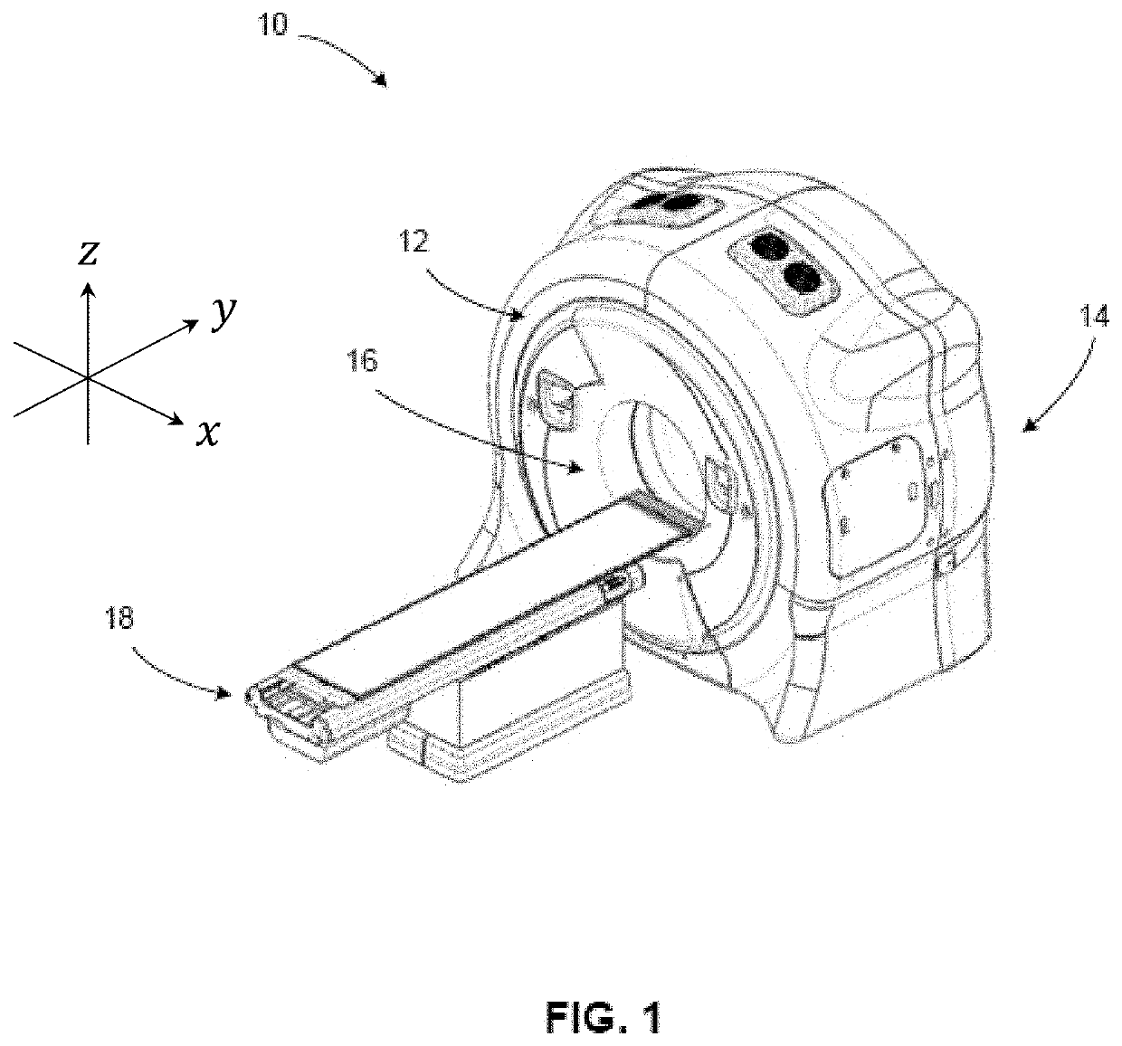
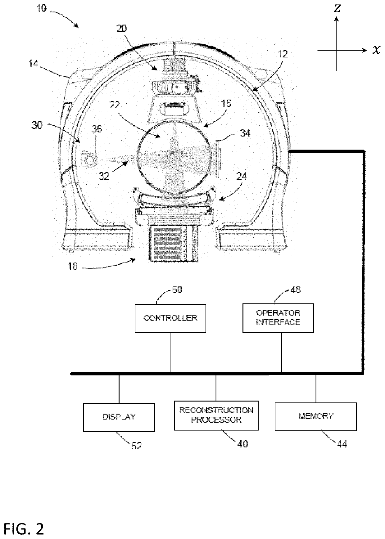
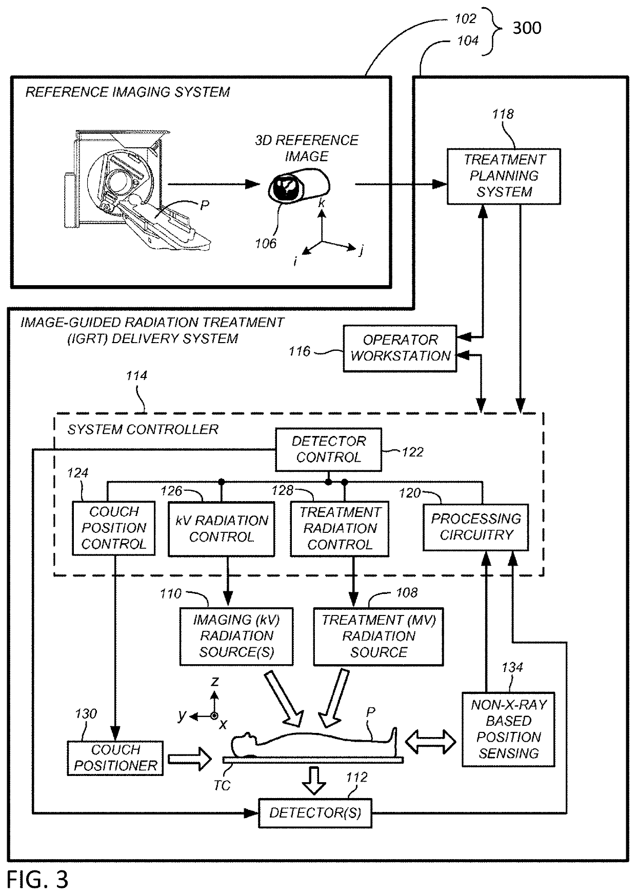
Multimodal imaging apparatus and methods include a rotatable gantry system with multiple sources of radiation comprising different energy levels (for example, kV and MV). Fast slip-ring technology and helical scans allow data from multiple sources of radiation to be combined or utilized to generate improved images and workflows, including for IGRT. Features include large field-of-view (LFOV) MV imaging, kV region-of-interest (ROI) imaging, and scalable field-of-view (SFOV) dual energy imaging.
Application Information
Patent Timeline
Application Date:The date an application was filed.
Publication Date:The date a patent or application was officially published.
First Publication Date:The earliest publication date of a patent with the same application number.
Issue Date:Publication date of the patent grant document.
PCT Entry Date:The Entry date of PCT National Phase.
Estimated Expiry Date:The statutory expiry date of a patent right according to the Patent Law, and it is the longest term of protection that the patent right can achieve without the termination of the patent right due to other reasons(Term extension factor has been taken into account ).
Invalid Date:Actual expiry date is based on effective date or publication date of legal transaction data of invalid patent.
Patent Type & AuthorityApplications(United States)

