Heat sink apparatus for microwave magnetron

Active Publication Date: 2020-06-04
TSENG TON RONG +1
View PDF0 Cites 2 Cited by
  • Summary
  • Abstract
  • Description
  • Claims
  • Application Information

AI Technical Summary

Benefits of technology

[0010]Accordingly, it is an object of the present invention to provide a heat sink apparatus for a microwave magnetron that utilizes heat pipes to dissipate the heat. Thus, by comparing

Problems solved by technology

Nevertheless, the magnetron might have some shortcomings such as narrower work bandwidths, less adjustability in frequencies, and huge heat dissipation needs within a tiny volume.
Further, for the magnetron dissipated by a water-cooling set, a poor heat dissipation efficiency may be met while a jam occurs i

Method used


Image

  • Heat sink apparatus for microwave magnetron
  • Heat sink apparatus for microwave magnetron
  • Heat sink apparatus for microwave magnetron

Examples


first embodiment

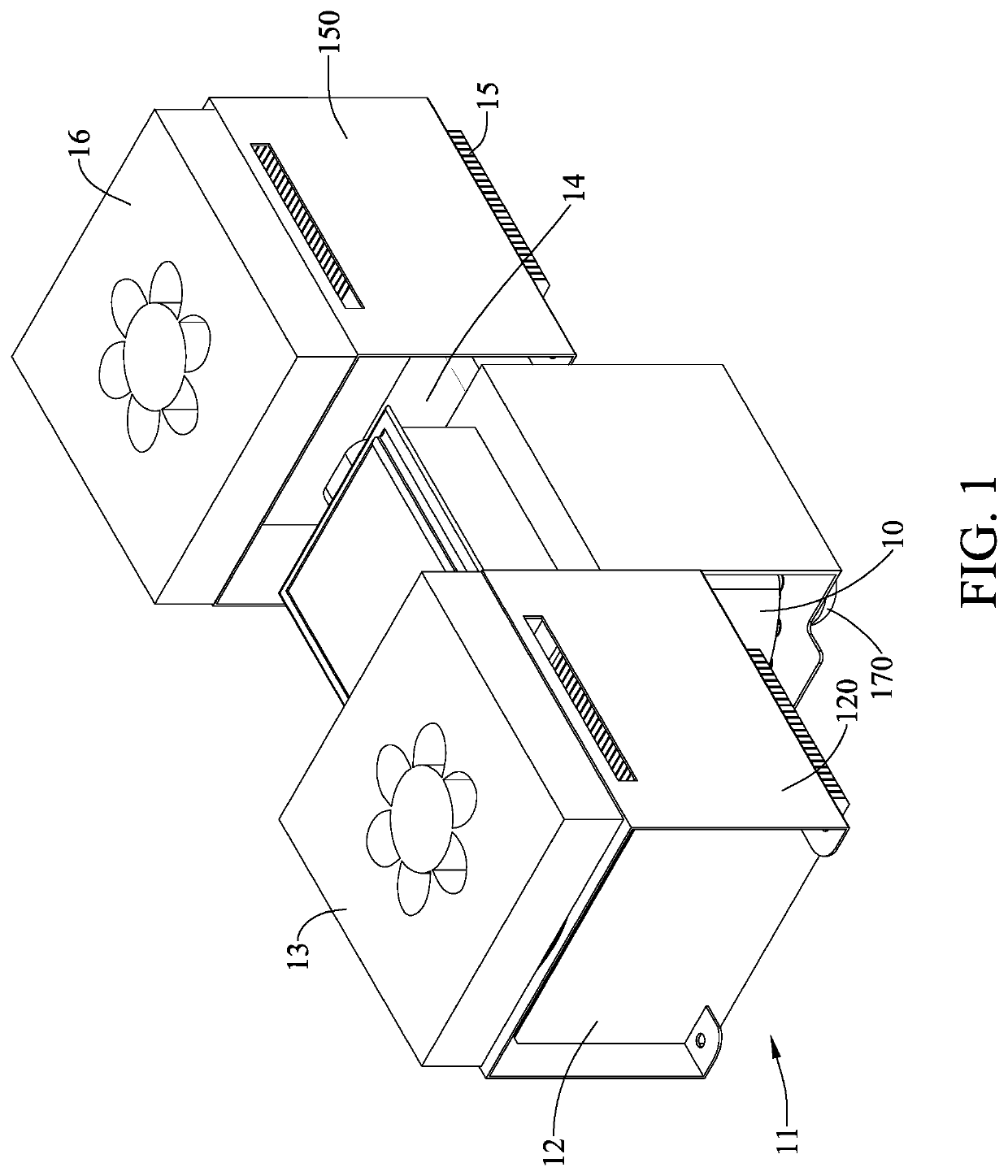
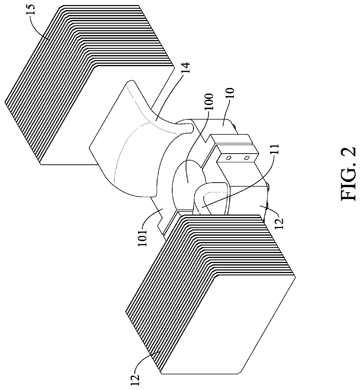
[0029]Referring now to FIG. 1 and FIG. 2, the heat sink apparatus for a microwave magnetron is shown. The heat sink apparatus includes a thermal conduction seat 10, at least one first heat pipe 11, a first heat-fin set 12, a first heat-dissipation fan 13, a at least one second heat pipe 14, a second heat-fin set 15 and a second heat-dissipation fan 16.

[0030]The thermal conduction seat 10, made of a conductive metal (a copper for example), has a central hole 100 for allowing an output antenna 170 of a microwave magnetron 17 to penetrate therethrough. Further, the thermal conduction seat 10 has a first block 101 and a second block 102. A first half-moon cavity is formed to one side of the first block 101, and a second half-moon cavity is formed to another side of the second block 102. As the first block 101 and the second block 102 are paired together to form the thermal conduction seat 10, the first half-moon cavity and the second half-moon cavity would be integrated together to form...

second embodiment

[0048]Referring now to FIG. 5 and FIG. 6, the heat sink apparatus for a microwave magnetron is shown. This embodiment include a thermal conduction seat 24, at least one first heat pipe 22, a first heat-fin set 21 and a first heat-dissipation fan 20.

[0049]The thermal conduction seat 24 has a central hole 242 for allowing an output antenna of a microwave magnetron 25 to penetrate therethrough. Further, the thermal conduction seat 24 has a first block 240 and a second block 241. A first half-moon cavity is formed to one side of the first block 240, and a second half-moon cavity is formed to another side of the second block 241. As the first block 240 and the second block 241 are paired together to form the thermal conduction seat 24, the first half-moon cavity and the second half-moon cavity would be integrated together to form the central hole 242 of the thermal conduction seat 24.

[0050]The first heat pipe 22 can be a flat heat pipe or a plurality of heat pipes. One end of the first h...


PUM


Abstract

A heat sink apparatus for a microwave magnetron includes a thermal conduction seat, a first heat-fin set, and at least one first heat pipe. One end of the first heat pipe protrudes into the thermal conduction seat, while another end of the first heat pipe protrudes into the first heat-fin set. An antenna of the microwave magnetron is to penetrate through the thermal conduction seat.

Description

CROSS REFERENCE TO RELATED APPLICATION[0001]This application claims the benefit of Taiwan Patent Application Serial No. 107142859, filed on Nov. 30, 2018, the subject matter of which is incorporated herein by reference.BACKGROUND OF THE INVENTION(1) Field of the Invention[0002]The invention relates to a heat sink apparatus for a microwave magnetron, and more particularly to the heat sink apparatus that can provide better heat dissipation performance for microwave magnetrons.(2) Description of the Prior Art[0003]Versatile applications in microwave technology are mainly attributed to two inventions in 30's: the magnetron and the waveguide. Actually, in world war II, the microwave technology has been successfully used to develop radars and communicative components.[0004]After world war II, besides more widely applications in military technology, output powers and energies in applications of the microwave and the magnetron have been enhancing. Further, the applications are also extended...

Claims


Application Information

Patent Timeline
IPC IPC(8): H01J23/00H01J25/50H05K7/20
CPCH01J25/50H01J23/005H05K7/20H05B6/642
Inventor TSENG, TON-RONG
Owner TSENG TON RONG
Why Eureka
Try Eureka